Page 7
SKU 45656
For technical questions, please call 1-800-444-3353.
ASSEMBlY INSTRUCTIONS
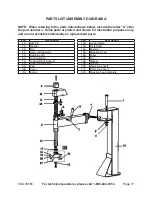
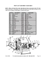
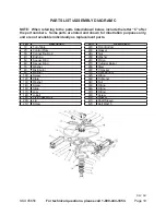
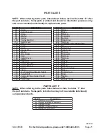
NOTE: All parts below refer to the parts listed on pages 17 through 22 of this
manual.
1.
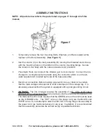
Temporarily remove the
four
mounting Bolts, Washers, and Nuts located at the
top/rear of the Body Assembly.
(See Figure F.)
2.
Set the column (C) on the body assembly (B) insuring the threaded studs line up
with the mounting holes on the bottom of the column mounting flange. Secure
the column to the body with the nuts and washers (A) provided.
3.
Pneumatic Hook Up: Connect the inflation gun to its connector. Connect the tire
changer to a compressed air network using the connector which is on the air-
water separator (D) located right side of the base assembly.
4.
Electric at connection: Before making any electric link up, check to be certain
that the main voltage corresponds to what is stamped on the voltage tag. It is
absolutely essential that the system is equipped with a good grounding circuit.
5.
WARNING:
The Tire Changer requires the assembly of a UL, CSA, or CE listed,
220 Volt, 3-Prong Electrical Plug (not provided) onto the unit’s electrical power cord.
The National Electric Code requires that the GREEN wire on the unit must be used
as the GROUND wire. The “HOT” wires on the power cord are the BLACK and
WHITE wires. Do not attempt to alter the 220 Volt, 3-Prong Plug or its assembly to
the power cord (as mentioned above) in any way. In addition, it is recommended
that this assembly procedure be carried out by a qualified technician.


