


CENTENT COMPANY
INTERPRETING Figure 12 – Optimum Damping
Figure 12 - optimum damping, reveals considerable detail about the motor’s dynamic
response. In this example, a 1000-line encoder was used on a size 23 servo motor with no
load attached. The power supply was 28 VDC and the Step generator frequency was 20.0
kHz for a motor speed of five revolutions per second.
By changing the direction while keeping the step rate constant, the motor is being asked to
reverse instantly. This is a physical impossibility.
The motor responds by decelerating as rapidly as it can, reversing direction, and then
accelerating in the new direction until it approaches the moving command position. It then
decelerates until its speed and position exactly matches the moving command position in the
new direction.
In this example, the time to go from five revolutions per second in one direction to five
revolutions per second in the opposite direction takes just three milliseconds. At this point,
the motor is 5.4 degrees behind the moving command position. In Figure 12 this is the
bottom of the Position Error notch ((0.6 volt amplitude
÷
.01 volts per increment of motion)
x
.09
°
per encoder count = 5.4
°
).
From 3 mS to 7 mS the motor catches up to the moving command position. In Figure 12 this
is the upward slope from the bottom of the notch until it crosses the 1.25 volt level.
From 7 mS to 10 mS the motor slightly overshoots (by .36 degrees) and then returns to match
the moving command position. From then on the motor’s speed and position matches the
moving command position within .09 degrees. This outperforms a step motor by a
considerable margin.
PICKING A MOTOR
It can be a challenge to pick the right motor for an application. This process can be made
easier if a few fundamentals are observed.
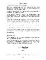
The first requirement is to determine how much power will be needed to drive the load. First
measure or calculate the maximum torque required, in ounce-inches, and the maximum
speed, in revolutions per minute (RPM), at which the motor must deliver this torque. Use
Equation 2 to calculate the power in Watts necessary to accomplish this.
8
.
1351
IN
OZ
RPM
WATTS
T
S
P
−
×
=
Equation 2
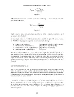
Next, select a motor voltage rating, typically 24 VDC or 48 VDC. Use Equation 3 to pick the
Stall Current, in amps, of the smallest possible motor to drive this load.
27
Summary of Contents for CN0182
Page 4: ......