


CN0182 PULSE INCREMENTAL SERVO DRIVE
D1
D2
D3
D4
D5
B1
C1
T1
115 VAC
BATTERY
CHARGER
SUPPLY GROUND
+ 18 to 80 VOLTS DC
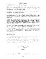
B1 = NICKEL-CADMIUM BATTERY
D5 = BATTERY DIODE
C1 = FILTER CAPACITOR
T1 = POWER SUPPLY TRANSFORMER
D1, D2, D3, D4 = BRIDGE RECTIFIER
3
4
+
+
Figure 8
When the motor begins to draw current in excess of the power supply rating, the power
supply voltage begins to sag and the diode begins to conduct current from the battery,
supplying the temporary current necessary for acceleration. Once the load eases, the power
supply voltage rises and turns off the current from the battery. The trickle-charger restores
the charge drained from the battery.
High currents through long, light gauge wires will result in a significant voltage drop. This
voltage drop can be enough to cause the CN0182 go into Under-Voltage Protect and reset.
This will then cause the motor to develop a Position Error Limit and Fault Output. The result
is the motor will have less performance than expected since it would have to be accelerated
more slowly to avoid drawing this level of current.
IMPORTANT!
Power supply wires must be heavy (16 gauge maximum) and as short in
length as possible. This is especially true for large, high current motors.
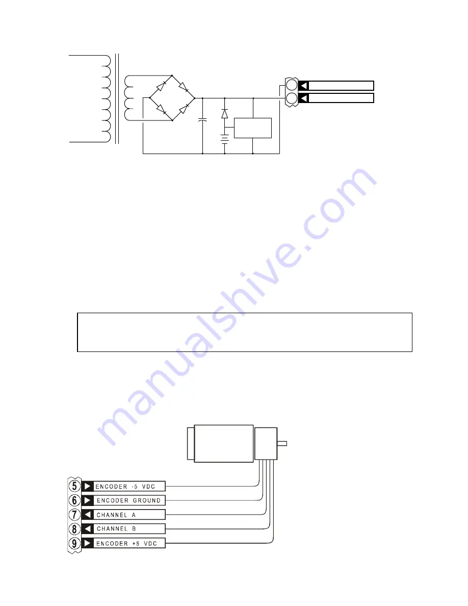
ENCODER GROUP
TERMINALS 5-9
Terminals 5 through 9 form the encoder interface, providing closed loop feedback to the
drive. The CN0182 provides regulated 5 volt outputs to power digital or analog encoders.
Analog encoders normally
require a bipolar power
supply while digital
encoders will generally use
only a +5 volt supply.
Terminal 9 is the +5 VDC
encoder power supply
output required by digital
(TTL) quadrature encoders.
The output provides a
maximum of 100 mA of
current. Most TTL encoders
12
Summary of Contents for CN0182
Page 4: ......