CellScale UniVert User Manual Download Page 109

UniVert User Manual 

104 


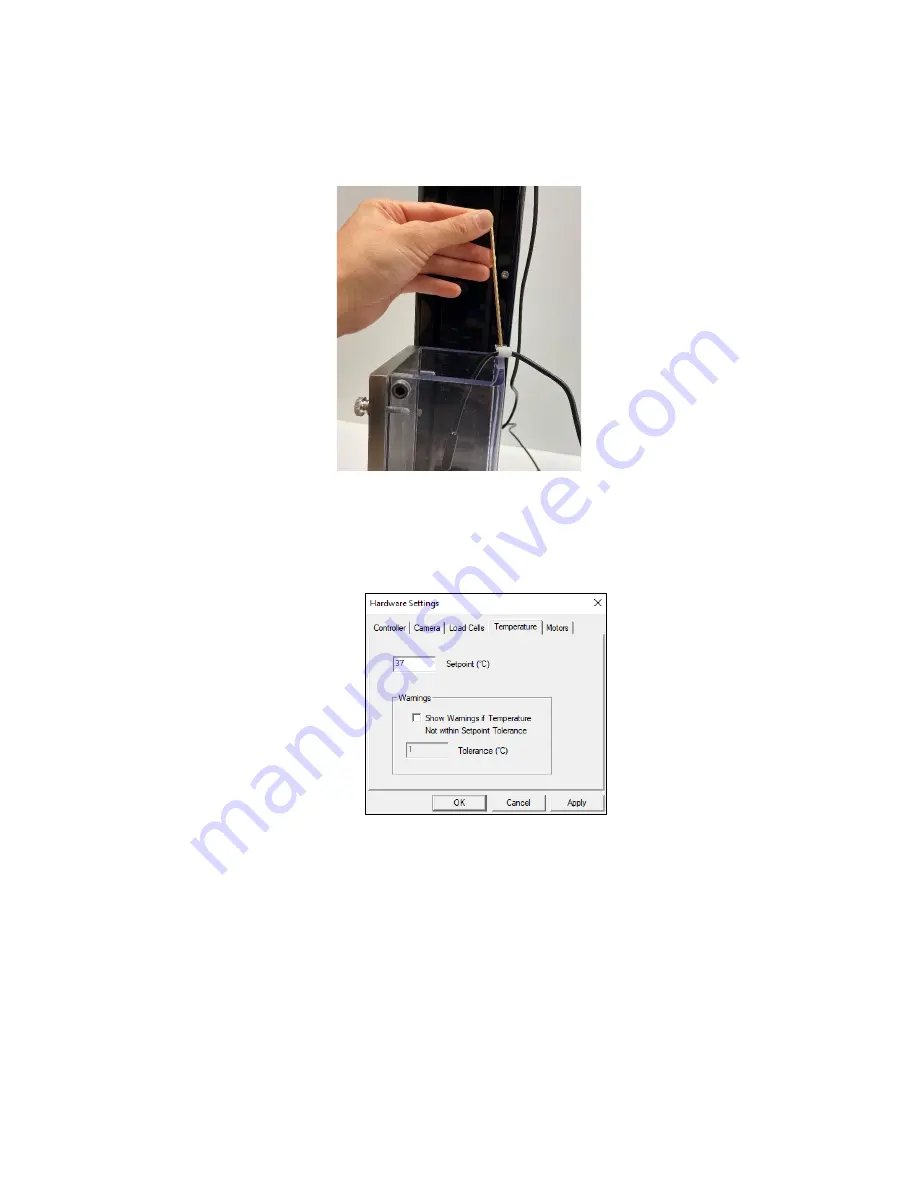
8.  Secure the temperature sensor to the top of the chamber using an M4x8 Flat head 

fastener and the supplied D-clip 


9.  To activate the fluid chamber heater, the unit must be powered on and the heater cable 

must be connected (the computer and software do not need to be on yet). At this point, 
the heater will warm the fluid to the last used temperature set point. The temperature set 
point can be changed by selecting Hardware from the Settings menu.  


10.  Typically, the heater will take 30 to 60 minutes to warm a full fluid chamber from room 

temperature to 37°C and will take up to 90 minutes to stabilize at this temperature. 


Summary of Contents for UniVert

Page 1: ...UniVert Mechanical Test System User Manual version 3 0 ...

Page 2: ...niversity of Waterloo We understand research and aim to provide effective solutions at a reasonable price Explore our web site www cellscale com or contact us to learn more about our measurement systems 2021 CellScale All rights reserved This material may not be reproduced displayed modified or distributed without the express prior written permission of the copyright holder For permission contact ...

Page 3: ...gurations 7 Software Overview 8 Output Files and Data Structures 9 Setting Up Starting a Test 10 Overview 10 Step 1 Start a New Test 10 Step 2 Reset the Actuator 11 Step 3 Specify Test Type 12 Step 4 Zero the Load Cell occasionally 12 Step 5 Modify Testing Parameters optional 13 Step 6 Mounting a Specimen 15 Platen Mounted Specimens 15 Grip Mounted Specimens 16 3 Point Bend Specimens 18 Step 7 Exe...

Page 4: ...e Strains Option 36 Data Overlay 37 Exporting Tracked Data 38 Exporting Images and Movies 40 System Hardware Settings 41 Controller 41 Load Cell 41 Actuator and Motor 42 Temperature 43 System Calibration and Advanced Tools 44 Load Cell Calibration 44 Attached to System 44 Calibration Plates 47 Zero Position Calibration 49 Custom Position Calibration 51 System Stiffness Compensation 52 Snap Image F...

Page 5: ... Horizontal Configuration 87 3 Point Bend Test Setup 89 Appendix E Camera Setup 92 Webcam 92 Scientific Camera 93 Appendix F Media Bath Setup 99 Vertical Media Bath 99 Horizontal Media Bath 106 Appendix G Changing Grip Springs 112 Appendix H Low Force Load Cells 116 Tension Test Setup 117 Vertical Configuration 118 Horizontal Configuration 120 Changing Grip Springs 122 Compression Test Setup 125 V...

Page 6: ...a Connections 1 USB for camera PC communication USB 3 0 for scientific camera 1 USB for controller PC communication System Assembly Some basic assembly and setup is required An unboxing and setup guide can be found in Appendix A Load cell installation is detailed in Appendix B and software installation is described in Appendix C Test setup and configurations are described in Appendix D Camera setu...

Page 7: ...reen LED and the Emergency stop switch E stop is rightmost The E stop will stop power to the motor and instruct the software to stop a test if one has been executed If the E stop has been depressed it must be rotated to return it back to its original position The E stop should only be used in emergency situations only since it will require a power cycle and actuator reset to set up a new test afte...

Page 8: ...cimen to its physiological or in vivo state During the process of specimen storage and preparation a specimen may swell dry out have its material fibers realign or its molecules reorganize It may take multiple preconditioning cycles for a specimen to be restored to its natural state Reproducing Physiological Conditions During Testing By applying various loads and load rates natural expansion and c...

Page 9: ...ed a test set Finally a test sequence is made up of multiple test sets The above example describes the following The entire diagram presents a full test sequence Within that sequence there are two test sets the first set applies preconditioning to the specimen the second set executes the actual test on the specimen Within the first set preconditioning two identical test cycles are implemented to b...

Page 10: ...pendent on the nature of the testing Recovering The recovery phase is the time during which the force being applied to the specimen is removed The duration of the recovery time is configurable and dependent on the nature of the testing Resting Finally the rest phase is the time between the end of one cycle and the beginning of the next Some tests may specify a short recover time or no recover time...

Page 11: ... displacement at a constant nominal rate This is equivalent to engineering strain or constant velocity The sinusoid function applies the displacement according to a sinusoid with the desired displacement magnitude and duration The UniVert system approximates this with a series of linear segments Under force control The ramp function applies the force at a constant nominal rate This is equivalent t...

Page 12: ...ation and tension forces are positive Compression Test This test mode is used in combination with provided compression platens In this mode positive displacement is in the direction of decreased fixture separation and compressive forces are positive The UniVert can be used in two configurations vertical and horizontal see Appendix D for more details The above test modes are all compatible in both ...

Page 13: ...est template review The data collection module is used to set test parameters enable specimen loading and testing and monitor test progress The screen layout for this module is shown below The image review and analysis module is used to playback accelerated or decelerated test images perform image analysis and tracking and output movie files for presentation purposes The screen layout for this mod...

Page 14: ...d in this directory The Images subfolder usually contains any recorded jpg images from a test These may also be stored in the main data folder While using the Analyze and Review software module you may create additional data files such as text files csv containing tracking results images with force data or tracking results overlaid wmf or movie files avi These additional files can be stored in the...

Page 15: ...ameters optional Step 6 Mount the Specimen Step 7 Execute the Test Step 8 Terminate the Test Prematurely optional Step 9 Saving the Template optional If this is your first time setting up the UniVert system please complete the steps in Appendix A Unpacking and Initial Setup prior to executing a test Step 1 Start a New Test Launch the UniVert software and then select Collect New from the File menu ...

Page 16: ... are ensuring that the displacement measurements taken by the UniVert are accurate dependent on an accurate Zero Position Calibration see System Calibration and Advanced Tools If you need to recalibrate the UniVert position see the Zero Position Calibration or Custom Position Calibration portion in the System Calibration and Advanced Tools section This is recommended if you are changing fixtures o...

Page 17: ...load cell at the start of a new test session With repeated use the zero point of the load cell can drift By zeroing the load cell you are ensuring that the force measurements are accurate The force offset can also be affected by changing the fixtures To zero the load cell select Zero Load Cell from the Tools menu or press on the toolbar System Alert You should zero the load cell after attaching a ...

Page 18: ...n the Test Sequence table and then pressing the Edit Set button or by double clicking on the desired row When you do so the Set Parameter Editor dialog will appear Note that displacements are specified in either strain or mm Force loads are specified in N and durations are specified in seconds The following table describes each of the parameters ...

Page 19: ...ion of a testing set Specimen size is adjusted after a preload adjustment Strain calculations are based on the specimen size after the last preload adjustment If you are working with a material for which preload values have been suggested you can set the value accordingly Otherwise zero is a good initial choice The preload accuracy is directly influenced by the resolution accuracy of the load cell...

Page 20: ...rol Alternatively the Move Actuator to Specified Size command may be used Ensure the correct size value is entered before clicking UniVert Tip Compression Specimen Mounting Make sure to center the specimen on the platen as much as possible to ensure accuracy in the force reading Ideally specimens will have two parallel flat sides and will make full contact with both platens Although this is not al...

Page 21: ...ciently far apart or enter the desired size and select Move to Specified Size 3 Attach the specimen to the top grip 4 Using Actuator Control lower the top grip with specimen attached 5 Open the bottom grip and lower the specimen between the grip surfaces Release the bottom grip UniVert Tip Specimen Thickness Measuring the specimen thickness before and or after a test is performed will allow stress...

Page 22: ...ently far apart 3 Loosen the M4 screw with a 2 5 mm hex key and squeeze the two halves of the top grip to clamp the sample For higher clamping force use the same hex key to tighten the locking screw against the back face of the grip 4 Using Actuator Control lower the top grip with specimen attached 5 Open the bottom grip and clamp the specimen between the grip faces Use the 2 5 mm hex key to tight...

Page 23: ...re some things to consider while handling a load cell The load cells are designed to handle overloads of up to 120 full scale value Overloading a load cell past this rating may cause permanent damage to the load cell Avoid applying excessive torque and transverse forces to the load cells Over tightening grips or platens onto the active end of the load cell may damage it Accidentally crashing the p...

Page 24: ...ted the actuators will maintain their current position In an emergency the Emergency Stop E Stop button can be pressed to stop the motor from moving This button will stop power to the UniVert acutator and allow it to be moved by hand The displacement position cannot be stored if the E Stop has been depressed Once the UniVert is ready to be used again twist the E Stop to return it to its original p...

Page 25: ...ult the new template will be stored in the current template directory You may change the template directory at the start of a new test in the Create Test from Template window If you would like to set a new template directory create a new folder in your Windows File Explorer and set this file path as the new directory in the Create Test from Template window You may delete templates through the File...

Page 26: ...ed name of each set Cycle Cycle and Phase information Time S Time point in seconds a data point was recorded Size mm Specimen Gauge Length at any given time Force N Load Cell reading Displacement mm Reports the change in size relative to the initial size Compensation mm Reports overall compensation due to system stiffness see the System calibration and Advanced Tools section Set to Off by default ...

Page 27: ...gs menu All these settings are specific to the test template selected Data Averaging The load cells are sampled at 100Hz with hardware using a central moving average of 8 samples Further data averaging can be applied to smooth noisy data by selecting Apply Averaging to Force Data and selecting a further central moving average ...

Page 28: ...xperiment Velocity Jog Integer mm s 1 0 039063 2 0 078125 3 0 15625 4 0 3125 5 0 625 6 1 25 7 2 5 8 5 9 10 10 20 UniVert Tip Testing Force Control Settings It is important to have appropriate Force Control Settings that match the materials you are testing To safely test Force Control Settings press on the tool bar or from the Tools menu select Move Actuators to Specified Load The dialogue shown on...

Page 29: ...ime s to achieve 20mm s Travel mm to achieve 20mm s 1 0 004 5 0000 50 0000 2 0 008 2 5000 25 0000 3 0 016 1 2500 12 5000 4 0 032 0 6250 6 2500 5 0 064 0 3125 3 1250 6 0 128 0 1563 1 5625 7 0 256 0 0781 0 7813 8 0 512 0 0391 0 3906 9 1 024 0 0195 0 1953 10 2 048 0 0098 0 0977 System Stiffness Compensation System Stiffness Compensation can be used to compensate displacement readings that occur in th...

Page 30: ...ed loads cannot be reached the actuators will keep moving until they reach the soft limits Min and Max Displacement in mm set the minimum and maximum positions to which the grips or platens can move These settings require adjustment especially when the fixtures are changed Max Force in N sets the maximum value of force at which a test will be automatically stopped The default value is set to the c...

Page 31: ...alitative feedback not for detailed analysis The graphs are updated at a maximum frequency of 10Hz certain short duration tests may not show all the detail that is present The graph settings can be specified by selecting Graphs from the Settings menu Auto scaling allows the axis min and max to start at the specified values but expand if the data values are larger or smaller than the initial limits...

Page 32: ...us Time This graph shows how the grips or platens are moving with time The phases of the test sequence and size adjustments due to preloading are readily apparent in this type of graph Force versus Displacement This graph displays a qualitative representation of the material behavior Viscoelastic effects like hysteresis and material response to different loading phases are apparent in this graph T...

Page 33: ...text file with a tst extension that contains information about the test parameters so that the software can display the images and data in a useful fashion The basic UniVert system comes with a Logitech HD 1080p webcam intended to be used for recording images for image playback and review This camera and software associated with it does not support image tracking For image tracking to be available...

Page 34: ...ges which have data associated with a particular tracking set Image Playback Options The controls on the left of the screen are broken into 2 sections Playback and Tracking The playback buttons allow the user to review the images taken during a test Next Prev Display next or previous image as dictated by Play Every parameter Play Stop Start and stop the playback Prev Next Cycle Jumps to a correspo...

Page 35: ...of the optimally located template To track an image follow these steps 1 Click the Create button in the tracking window shown above This brings up the Tracking Editor dialogue box 2 Enter a Tracking Name 3 Select Source Image in the test image list tree and click Set to the right of the Source box 4 Select the Target Images in the test image list tree and click Set to the right of the Target box T...

Page 36: ...UniVert User Manual 31 ...

Page 37: ... in the sequence Previous Image Tracking tends to have good correlation for each individual step but is prone to error accumulation since each step is independent The best method for a given data set will depend on the number of images and the content of the images Sometimes it is best to use Previous Image Tracking but to only use every other image or every nth image rather than all the images av...

Page 38: ...icking the Details icon brings up the window shown to the right Options include changing the point radius or color showing ID numbers and showing gridlines with or without ID numbers Gridline ID numbers are associated with each grid square cell while Point ID numbers are associated with the points themselves Tracking display settings default to the last used settings Figure 1 Initial tracking grid...

Page 39: ...e test controller extracts images from this buffer at the specified frequency specified in the Set Parameter Editor 5Hz 1Hz 0 1Hz 0 01Hz or 0 001 Hz These images are written to the output directory The file name is the ideal capture time The actual capture time may differ from the ideal capture time by as much as 1 30 of a second since the images are extracted from a buffer The test software creat...

Page 40: ... this difference be significant This log stores the actual capture time and the idealized capture time The camera default shutter and gain are specific to each test template and can be set by selecting the Camera tab in Hardware from the Settings menu The recommended maximum shutter speed is 10mS Typically the camera iris is left fully open and the shutter and then the gain are adjusted to achieve...

Page 41: ...test Clicking the details icon brings up the window shown to the right This dialogue allows the user to change the reference image as well as the appearance of the circles and text Showing text for E1 E2 will result in the text showing the principal strains along the major and minor axis of the ellipse Showing text for Ex Ey will result in text showing the strains along the X and Y directions rega...

Page 42: ...aph box displays this data as a graph overlaid on the images Clicking the details icon displays the window shown to the right The dialogue allows the user to change the size and appearance of the overlaid graph The data points associated with the current image are marked on the graph with green circles The overlaid data graph will be drawn on top of any image tracking displays when they overlap Da...

Page 43: ...images in the test image list tree and pressing the set button When exporting strains data from Selected Tracking Points all four points of a grid cell need to be selected for data from that cell to be exported Exported data is labeled with associated ID numbers grid point ID numbers for exported coordinates and grid cell ID numbers for exported strain values To display ID numbers on tracking grid...

Page 44: ...UniVert User Manual 39 Figure 6 Tracking Grid showing ID Numbers Figure 7 Sample Exported Data ...

Page 45: ...ews including all displayed tracking grids tracking data and overlaid data as an avi movie select Movie from the Export menu The dialogue shown on the right will be displayed The image list is automatically set to the currently selected images in the test image list tree This image list can be changed by selecting new images in the test image list tree and pressing the Set button Options are avail...

Page 46: ...s or thermal drift temperature changes or prolonged loading can introduce small offsets It is recommended that the zero load state be redefined before beginning a test This can be done by selecting Zero Load Cells from the Tools menu or selecting The load cells are sampled at 100Hz with hardware providing an 8 sample averaging to reduce noise in the data Further sample averaging can be implemented...

Page 47: ...e Excessive thrust loads should only occur if mechanical interference obstructs the movement of the actuator It is advisable to reset the actuators occasionally The acceleration and velocity parameters can be modified in the Advanced Settings window if necessary for your materials or experiments see the Advanced System Settings Dialogue section for more details If the Emergency Stop E Stop button ...

Page 48: ...ilize at this temperature When Show Temperature Warnings is enabled and the Current Temperature is not at the Temperature Set Point plus or minus the specified tolerance a red indicator button will be displayed next to the Current Temperature live output and a warning dialogue will appear when you execute the test System Alert In the event of a dislodged or faulty temperature sensor or if there is...

Page 49: ...d it is advisable to perform a load cell calibration This process will require a set of calibration weights not included with system Load cells can be calibrated attached to the UniVert system or with the Calibration Plates Attached to System 1 Attach the load cell to the fixed end of the UniVert i e on the baseplate with an M5x16 SHCS and 4mm hex key Ensure the measuring end of the load cell is f...

Page 50: ...y 4 From the Tools menu select Load Cell Calibration 5 Zero the load cell to remove the weight of the platen from the calibration values measured 6 Measure the zero load condition for the first calibration point no calibration weight a Enter 0 in the Enter Weight dialogue b Click Read ...

Page 51: ...oad cell range However at least one weight of at least 50 of the load cell range is recommended 10 Click Run 11 Check the Relative Calibration Factor and Absolute Calibration Factor for reasonable values The Relative Calibration Factor is a ratio of the new calibration factor to the previous calibration factor Ideally this value should be between 0 99 1 01 The Absolute Calibration Factor is the ac...

Page 52: ...nsure the cable is still connected to the UniVert 2 Attach the two provided calibration plates to both ends of the load cell 3 Orient the setup such that the measuring end of the load cell is facing up and continue with the standard calibration procedure described above Note Calibration plates are only compatible with regular UniVert load cells Low force load cells may only be calibrated while att...

Page 53: ... this rating will cause permanent damage or failure Avoid applying torque and transverse forces to the load cells Over tightening grips or platens onto the active end of the load cell may damage it Accidentally crashing the platens or grips together will produce more force than most load cells can handle Be careful and reduce speed when jogging grips close together Generally avoid dropping tapping...

Page 54: ...should be re calibrated on initial system setup and whenever the grips platens load cells or risers are changed Changing these components will always alter the zero position slightly There is a software utility to automatically calibrate the zero position using a spring of known length provided with the UniVert system The calibration spring is placed between the grips or platens The calibration ut...

Page 55: ...ngth mm This figure is provided for each spring included in the UniVert system 5 Using the jog buttons move the actuator such that there is a small gap between the top of the spring and the bottom of the upper platen or grip Do not contact the top of the spring Using a slow jog speed below 5 is advisable for this reason 6 Select Run and let the calibration utility proceed The software will calibra...

Page 56: ... position 1 Jog the fixtures so their distance is within the reading range of the calipers 2 Measure the distance between the fixtures with the calipers Ensure the calipers are reading in millimeters 3 Open the Custom Position Calibration utility in the Tools menu 4 Enter the distance read out by the calipers in mm and press Set to define a new custom position ...

Page 57: ...her than 1 0 and a specimen size of 9 1 mm rather than 9 mm Note The system stiffness compensation does not affect or alter the applied loads or displacements only the reported values in the output csv files The amount of compensation being applied to the displacement and size columns of the output data file can also be shown as an additional output column see the Additional Settings section UniVe...

Page 58: ...ensation spacer that is provided a small washer onto the exact center of the lower platen After placing the calibration spacer slowly jog the platens together until there is a very small gap between the upper platen and the spacer If this gap is too large the software utility will take a very long time to run However do not allow the upper platen and the spacer to come in contact If the platens cr...

Page 59: ...rt the calibration and set the stiffness compensation value 5 Press OK to Reset Actuators and complete the calibration 6 The calculated system stiffness compensation value will be displayed in the message window The calibration utility will slowly drive the platens together until the full scale load is reached on the load cell Resulting load displacement data is typically very linear and a best fi...

Page 60: ...tware is available you may download it from our website www cellscale com downloads To update the firmware 1 Connect the UniVert to the PC via USB and turn on power to the UniVert 2 Open the UpdateFirmware exe program located in Univert Software Utilities Update Firmware 3 The program will automatically update the firmware of the UniVert 4 Power cycle the system after the firmware is successfully ...

Page 61: ...ed on launch the manual firmware update software located in UniVert Utilities Update Firmware Advanced 2 Click the Connect button 3 Load the firmware file using the Browse button The file will be a bin extension 4 Execute the update using the Update button 5 Power cycle the system after the firmware is successfully updated before using the UniVert software again ...

Page 62: ...p USB cables between the computer and UniVert are disconnected The supply power surges or is interrupted When a communication error occurs close UniVert software check connections power cycle the UniVert Device and restart the UniVert software Be sure to reset the actuators before setting up a new test UniVert Tip Preventing Power Disruptions We recommend plugging the UniVert and host computer int...

Page 63: ...d this there are several software warnings which occur under these circumstances Moving the actuator out of range with Move to Force If the actuator is moved past the range limit when using Move to Force the UniVert software will display an error message shown below It is recommended to perform an actuator reset before continuing testing You may need to adjust the range limits by selecting Range L...

Page 64: ...ll terminate the test and display an error message UniVert Tip Zero Position Calibration Perform a zero position calibration see the System Calibration and Advanced Tools section when the load cell grips or risers are changed A correct zero position will ensure that the failsafe features for the actuator limits described above will work as intended ...

Page 65: ...llow the switch to pop out again This switch is intended to be used only in case of EMERGENCY as the actuator will lose its position when the E Stop has been depressed Once the E Stop has been returned to its original position after the being activated power cycle the UniVert and reset the actuators to restore the position accuracy A test cannot begin until an actuator reset has been completed aft...

Page 66: ...system setup A clearance space L x W x H of 25cm x 35cm x 60cm and 60cm x 35cm x 25cm is required for vertical and horizontal configuration setup respectively Tools Hex keys 2 5mm 3mm 4mm and 5mm Components Item Name Item Quantity UniVert Main Unit 1 Pivot Wings 2 Motor Bracket A 1 Motor Bracket B 1 Horizontal Bracket No Load Cell 1 ...

Page 67: ...t User Manual 62 M5 Tension Load Cell Bracket 1 M3 Tension Load Cell Bracket 1 Load Cell 1 Calibration Plates 2 Light Grip Springs 3 Medium Grip Springs 3 Heavy Grip Springs 3 M3 Compression Platen Plastic 1 ...

Page 68: ...anual 63 M5 Compression Platen Stainless Steel 1 M5 Compression Base Riser Tall 1 M5 Compression Base Riser Short 1 M3 Specimen Grip Plastic 1 M5 Specimen Grips Stainless Steel 2 M5 Locking Discs 2 M3 Locking Discs 2 ...

Page 69: ...UniVert User Manual 64 M5 Coupling Nut 1 M5 to M3 Thumbnut 1 M5 Stand Off 1 Calibration Spring 1 Sample Test Specimens 4 Stiffness Compensation Spacer 1 Camera 1 ...

Page 70: ...B to Motor Bracket A 4 M5x12 SHCS Attach Horizontal Fixtures M5 see Appendix D for more details Mount loadcell or fixtures to Motor Bracket B 4 M3x12 SHCS Attach Horizontal Fixtures M3 see Appendix D for more details 1 M5x16 SHCS Mount fixtures to baseplate 1 M4x25 FHCS To increase clamping force of M5 Specimen Grips 2 SHCS Socket Head Cap Screw FHCS Flat Head Cap Screw ...

Page 71: ...UniVert User Manual 66 Step 1 Unpack the main unit and the accessories Set aside the main unit Pivot Wings 4 x M4x8 SHCS Motor Bracket B 4 x M4x8 SHCS and 3mm hex key ...

Page 72: ... Motor Bracket B to Motor Bracket A Attach the Motor Bracket with 4 x M4x8 SHCS using the 3mm hex key Step 3 Attach the Pivot Wings to the main unit Attach both Pivot Wings to the side of the UniVert with 4 x M4x8 SHCS using a 3mm hex key ...

Page 73: ...oper connection To connect a load cell align the keyway push the connector in and turn the threaded locking ring until tight Note that this may require several turns to lock in place The temperature probe and heater connectors also have a keyway Align the red marks on both the panel connector and cable connector These connectors will only be present if a Media Bath package is purchased with the Un...

Page 74: ...Vert is ready for testing Step 9 Calibrate the Load Cell See the System Calibration and Advanced Tools section of this User s Manual for more information Step 10 Set the Actuator Zero Position See the System Calibration and Advanced Tools section of this User s Manual for more information Step 11 Begin Testing It is recommended that the User s Manual be thoroughly reviewed before beginning testing...

Page 75: ... time or changing load cells 1 Identify the active end of the load cell see below image This is the MEASURING END of the load cell which results in a force reading This end is covered with a small plate not continuous with the rest of the load cell body 2 Attach the appropriate thumbnut coupling to the NON MEASURING END of the load cell M5 or M3 depending on the load cell ...

Page 76: ... Bracket B with an M5x12 SHCS using a 4mm hex key For horizontal configuration mount it to the baseplate of the UniVert with an M5x16 SHCS using a 4mm hex key 4 The measuring end of the load cell should be exposed and the non measuring end attached to the thumbnut coupling and then to the UniVert The test fixtures are ready to be mounted to the load cell ...

Page 77: ... The package contains the software installer for the user interface and control software for the UniVert To install the software 1 Go to the provided web address and download the compressed installation package 2 Transfer this file to the computer which will be running the UniVert device 3 Right click on the folder and select Extract All to unzip 4 After this is complete go to the uncompressed ins...

Page 78: ...UniVert User Manual 73 ...

Page 79: ...UniVert User Manual 74 ...

Page 80: ...UniVert User Manual 75 ...

Page 81: ...UniVert User Manual 76 ...

Page 82: ...UniVert User Manual 77 ...

Page 83: ...xtures For the horizontal configuration use the leftmost mounting hole on the baseplate for test fixtures Tension Test Setup Set the test mode to Tension Settings Test Mode Tension in the software This setting is specific to the test template being used and can be saved to a template Horizontal Configuration Mounting Hole Vertical Configuration Mounting Hole ...

Page 84: ...al 79 Vertical Configuration 1 Install the desired load cell see Appendix B to Motor Bracket B 2 Screw a locking disc onto the measuring end of the load cell Select either an M5 or M3 locking disc based on the load cell ...

Page 85: ...the actuator at any rotational position Finger tighten all components ie avoid using a wrench Beware of exerting excessive off axis and torquing forces to avoid damage to the load cell 4 Attach the M5 stand off to the base with an M5x16 SHCS screw using a 4mm hex key Use the mounting hole furthest from the power switch This may be easier to do with the UniVert in the horizontal configuration ...

Page 86: ...d align the two grips until they are parallel Loosen the locking discs to adjust the grips Once they are aligned hold the grips in place while tightening the locking discs 7 A Zero Position Calibration is required after changing grips or platens See the System Calibration and Advanced Tools section of this manual for more details ...

Page 87: ...se the mounting hole closest to the power switch 2 Install the grip to the Tension Load Cell Bracket For an M5 threaded load cell use the stainless steel M5 grip M5 Tension Load Cell bracket M5x12 SHCS 4mm hex key and M5 Locking Disc For an M3 threaded load cell use the plastic M3 grip M3 Tension Load Cell Bracket M3x12 SHCS 2 5mm hex key and M3 Locking Disc ...

Page 88: ... Bracket to the load cell and affix it with the corresponding locking disc The size of both these fixtures M5 or M3 will depend on the load cell selected 4 Attach the moving grip to the Horizontal Bracket No Load Cell with an M5x12 SHCS using a 4mm hex key ...

Page 89: ...d cell grip assembly only handle the assembly by the body of the load cell This is to prevent overloading or damaging the load cell 7 A Zero Position Calibration is required after changing grips or platens See the System Calibration and Advanced Tools section of this manual for more details If you are using the Horizontal Media Bath for your experiment an additional locking disc will be required f...

Page 90: ...saved to a template Vertical Configuration 1 Install the desired load cell see Appendix B to the Motor Bracket B of the UniVert 2 Attach the compression platen directly to the measuring end of the load cell Choose an M5 or M3 platen depending on the load cell Finger tighten all components Beware of exerting excessive off axis and torquing forces to avoid damage to the load cell ...

Page 91: ...4mm hex key Use the mounting hole furthest away from the power switch This will be easier to do when the UniVert is lying in the Horizontal configuration 4 A Zero Position Calibration is required after changing grips or platens See the System Calibration and Advanced Tools section of this manual for more details ...

Page 92: ... Tension Load Cell bracket M5x12 SHCS 4mm hex key and M5 Locking Disc b For an M3 threaded load cell use the plastic M3 platen M3 Tension Load Cell Bracket M3x12 SHCS 2 5mm hex key and M3 Locking Disc 2 Install the load cell assembly see Appendix B to the fixed end of the UniVert with an M5x16 SHCS and 4mm hex key Use the mounting hole closest to the power switch 3 Install the Tension Load Cell Br...

Page 93: ...tep to the Motor Bracket B with 2 x M5x12 SHCS 6 A Zero Position Calibration is required after changing grips or platens See the System Calibration and Advanced Tools section of this manual for more details If you are using the Horizontal Media Bath for your experiment an additional locking disc will be required for your set up Please see Appendix F for more details ...

Page 94: ... 3 Point Bending Block and sliders Attach M2x6 fasteners on the sides of the sliders and bending blocks Place 4 40 5 16 fasteners through the hole and the square nuts Place the square nuts through the groove of the bottom block Use the large O Rings and small O Rings as illustrated below to hold the 3 point bending dowels in place Note Choose a dowel size appropriate for the test being performed S...

Page 95: ...tion using the locking disc Finger tighten all components Beware of exerting excessive off axis and torquing forces to avoid damage to the load cell 6 Attach and align the 3 Point bend rail onto the baseplate with an M5x25 SHCS and wingnut This may be easier to do with the UniVert in horizontal configuration and tilted back ...

Page 96: ...UniVert User Manual 91 7 Secure both sliders on the rail in the desired position by tightening the fasteners with a 3 32 hex key ...

Page 97: ...h or without the camera plugged in To setup the camera follow these steps 1 Before starting the UniVert software plug the webcam into a USB port 2 Thread the tripod into the mounting hole on the bottom of the camera 3 Set the camera in the desired recording position using the flexible tripod 4 Refer to the System Hardware Settings section for additional camera settings ...

Page 98: ...he image tracking feature in the UniVert software First set up the camera positioning system The components and tools required are Rail 2 x M6x6 SHCS Rail Carrier Mounting Post Post Holder Post Collar 5mm hex key 1 Place the UniVert in the horizontal configuration 2 Install the camera rail with 2 x M6x6 SHCS using a 5mm hex key in the desired location along UniVert tower ...

Page 99: ...UniVert User Manual 94 3 Thread the Post Holder to the Rail Carrier 4 Slide the Rail Carrier onto the Rail and tighten the thumbnut at the back securely ...

Page 100: ... Mounting Post in the Post holder Ensure the M6 threaded hole is facing outward 6 Attach the Post Collar to the Mounting Post This is to ensure the post remains at the same height when adjusting the rotation with the Post Holder thumbnut ...

Page 101: ...uired are Camera with mounting plate Lens USB 3 0 cable 4 x M2x6 SHCS 1 5mm hex key Camera Bracket M6x6 SHCS 5mm hex key 1 Remove the lens caps from both the camera and lens and gently thread the lens onto the camera 2 Attach the Camera Bracket onto the camera assembly with 4 x M2x6 SHCS using a 1 5mm hex key ...

Page 102: ...unting Post with M6x6 SHCS using a 5mm hex key 4 Attach the USB cable to the Camera securing the USB locking screws and plug the other end into a USB 3 0 or higher port on the PC These are the typically labeled SS and or have a blue plastic tab on the connector ...

Page 103: ...mage brightness with the Hardware Settings in the software see the System Hardware Settings section 2 Obtain desired magnification level by manually adjusting the W T ring on the lens 3 Bring the image to optimum focus by manually adjusting the F N ring on the lens 4 Use the set screws on each of the lens rings to lock them at the desired settings Iris ring W T ring F N ring ...

Page 104: ...n a temperature controlled fluid Vertical Media Bath The components and tools required to set up the vertical media bath are Polycarbonate media chamber Heater plate Thumbnuts Temperature probe Heater cable O rings Circular nylon spacer M5x35mm SHCS 4mm hex key 2 5mm hex key Long M5 to M3 coupling Syringe ...

Page 105: ...o the Long Coupling Nut provided 2 Attach the load cell assembly from the previous step to the Motor Bracket B on the UniVert with M5x12 SHCS and jog the moving end near its upper limit This will allow for more room when installing the bath to the baseplate ...

Page 106: ...er 4 Attach the desired fixture and media chamber to the UniVert baseplate Ensure the fixture is fastened tight and compresses the O ring to ensure the chamber does not leak For compression tests align the compression platen over the polycarbonate chamber and fasten it to the baseplate with an M5x25 SHCS and 4mm hex key ...

Page 107: ...Vert User Manual 102 For tension tests align the plastic spacer under the M5 Stand Off and fasten it to the baseplate with an M5x35 SHCS and 4mm hex key Attach the locking disc and grip to the M5 Stand Off ...

Page 108: ...ertical position and place the heater plate in place Make sure the O ring on the back edge of the chamber is properly set and firmly fasten on the thumb screws 6 Attach the remaining grip or platen to the load cell 7 Attach all connections for heater and temperature sensor ...

Page 109: ...r cable must be connected the computer and software do not need to be on yet At this point the heater will warm the fluid to the last used temperature set point The temperature set point can be changed by selecting Hardware from the Settings menu 10 Typically the heater will take 30 to 60 minutes to warm a full fluid chamber from room temperature to 37 C and will take up to 90 minutes to stabilize...

Page 110: ...pecified tolerance a red indicator button will be displayed next to the Current Temperature live output and a warning dialogue will appear when you execute the test 12 Once your test is complete use the supplied syringe to remove the media from the chamber Ensure the bath is completely empty before removing the back plate from the polycarbonate chamber ...

Page 111: ...The components and tools required to set up the horizontal media bath are Plastic Fluid Dish Heater Plate Heater Pivot Wings with sleeve bearings 4x M4x16 SHCS Shoulder screws 3mm hex key Temperature probe Heater cable Extra M5 or M3 Locking Discs ...

Page 112: ...Mount the Heater Plate and Heater Pivot Wings assembly to the UniVert system with the supplied shoulder screws and 3mm hex key This will be easier to do with the UniVert in the vertical configuration 3 Place the UniVert back in its horizontal configuration Be careful when doing so as the heater plate will swing freely ...

Page 113: ... disc between the desired load cell and corresponding coupling 5 Attach the desired fixtures to the load cell in the Horizontal Configuration see Appendix D for more details Tilt the UniVert back as this will allow for more room when fastening the fixtures ...

Page 114: ...UniVert User Manual 109 6 Place the fluid dish on the Heater Plate and attach all the connections for the heater and temperature probe ...

Page 115: ...hamber heater the UniVert controller must be powered on and the heater cable must be connected the computer and software do not need to be on yet At this point the heater will warm the media to the last used temperature set point The temperature set point can be changed by selecting Hardware from the Settings menu ...

Page 116: ...ke up to 90 minutes to stabilize at this temperature 10 When Show Temperature Warnings is enabled and the Current Temperature is not at the Temperature Set Point plus or minus the specified tolerance a red indicator button will be displayed next to the Current Temperature live output and a warning dialogue will appear when you execute the test ...

Page 117: ...d with the UniVert and these may be switched at any time using the jig provided The light medium and heavy springs will provide 10N 20N and 40N of gripping force respectively To change a grip spring follow these steps 1 Gather the required tools Grip jig Screwdriver Grip Safety glasses recommended 2 To remove the current spring press both halves of the grip and place it inside the provided jig to ...

Page 118: ... to palm over the assembly to contain all the parts as it is removed from the jig System Alert A fully installed spring experiences a high amount of stored energy When removing the grip and spring from the jig be sure to maintain pressure on both halves of the grip Safety glasses are recommended when changing grip springs 5 Remove the dowel from inside the jig 6 Place the desired spring into the g...

Page 119: ...rip to the top and carefully press it down to compress the spring 8 Place the grip and new spring into the jig Again using two hands may make this step easier Use one hand to maintain pressure on the spring and the other to palm over the assembly to keep all components together ...

Page 120: ... pulling up UniVert Tip High Force Grips Tighten the M4 locking screw on the high force grips stainless steel with a 2 5mm hex key to increase clamping force if the heavy springs are not enough Do not use excessive force when tightening the screw Overtightening could strip the screw hex head or damage the specimen ...

Page 121: ...s assembled in grips Heavy springs Low force compression platen M3 male thread Plastic M3 Tension Load Cell Bracket M5 to M3 stand off long M5 to M3 stand off short M3 Coupling nut 2x M3x8 SHCS 2 5mm hex key All test fixtures should be mounted to the measuring end of the load cells The active measuring end of the low force load cells are shown below Due to their low capacity and sensitivity be car...

Page 122: ...re provided with the low force grips The light medium and heavy springs will provide 12N 24N and 60N of gripping force respectively 1 Set the test mode to Tension Settings Test Mode Tension This setting is specific to the test template being used and can be saved to a template 2 Attach the M5 to M3 stand off to the non measuring end of the low force load cell ...

Page 123: ...t B with an M5x12 SHCS using a 4mm hex key 2 Ensure the measuring end of the load cell is exposed and attach the M3 male thread grip directly to the measuring end of the load cell Finger tighten all components Beware of exerting excessive off axis and torquing forces to avoid damage to the load cell ...

Page 124: ... stand off 5 Align the grips to be parallel by loosening the M5 screw locking disc and rotating the load cell assembly grip Only handle the load cell assembly by the coupling or the sides of the loadcell Twisting the grip while it is attached to the load cell can result in overloading 6 A Zero Position Calibration is required after changing grips or platens See the System Calibration and Advanced ...

Page 125: ... Bracket with an M3x8 SHCS using 2 5mm hex key 2 Attach the load cell to the above assembly with an M3x8 SHCS using a 2 5mm hex key Finger tighten all components Beware of exerting excessive off axis and torquing forces to avoid damage to the load cell 3 Attach the load cell assembly to the baseplate with an M5x16 SHCS using a 4mm hex key ...

Page 126: ... Position Calibration is required after changing grips or platens See the System Calibration and Advanced Tools section of this manual for more details For use with the Horizontal Media Bath 1 Attach the shorter M5 to M3 stand off to the load cell 2 Follow the same remaining steps above to set up the horizontal configuration fixtures for use with the horizontal media bath The final set up should r...

Page 127: ...ngs will provide 12N 24N and 60N of gripping force respectively To change a grip spring follow these steps 1 Gather the required tools 2 5 mm hex key Grip Spring Calibration Plate Safety glasses recommended Small mallet and small screwdriver optional 2 To remove the current spring hold the grip with the pivot hole and dowel over top the M5 hole of the Compression Plate ...

Page 128: ...ace of the dowel in the pivot hold of the grip Carefully hold the grip with one hand while removing the hex key or screwdriver System Alert A fully installed spring experiences a high amount of stored energy When removing the spring from the grip be sure to maintain pressure on both halves of the grip Safety glasses are recommended when changing grip springs 5 Remove the dowel from inside the Comp...

Page 129: ...rip to the bottom and carefully press it down to compress the spring 8 Ensure the pivot hole of the grip halves are aligned and press the dowel into the grip If needed gently tap the dowel against the surface of the table or with a small mallet while holding the grip securely ...

Page 130: ...e supported by a supplementary riser not included with the UniVert to use the compression test setup in the horizontal configuration 1 Set the test mode to compression Settings Test Mode Compression This setting is specific to the test template being used and can be saved to a template 1 Attach the M5 to M3 stand off to the non measuring end of the low force load cell ...

Page 131: ...l Finger tighten all components Beware of exerting excessive off axis and torquing forces to avoid damage to the load cell 3 Attach the M5 Compression Base Riser Tall to the baseplate of the UniVert with an M5x16 SHCS using 4mm hex key This may be easier to do with the UniVert in horizontal configuration 4 A Zero Position Calibration is required after changing grips or platens See the System Calib...

Page 132: ...ow Force Compression Platen to the M3 coupling nut and affix it to the Plastic M3 Tension Load Cell Bracket with an M3x8 SHCS and 2 5mm hex key 2 Attach the load cell to the above assembly with an M3x8 SHCS and 2 5mm hex key Finger tighten all components Beware of exerting excessive off axis and torquing forces to avoid damage to the load cell 3 Attach the load cell assembly to the baseplate with ...

Page 133: ... 6 A Zero Position Calibration is required after changing grips or platens See the System Calibration and Advanced Tools section of this manual for more details For use with the Horizontal Bath 1 Attach the shorter M5 to M3 stand off to the load cell 2 Follow the rest of the steps to set up the remaining horizontal configuration fixtures The final set up should resemble the image below Copyright 2...

Reviews: