background image

 24V THERMOSTAT KIT WIRING INSTRUCTIONS

The 24V thermostat conversion kit requires a standard 18-5 thermostat wire to be run from the evaporator unit to the 

thermostat. The white wire will not be used, as there is no heating function. (Some thermostats need a common wire and 

some do not; the unit is equipped with a common wire if needed.)18-5 thermostat wire (communication cable) must be run 

between the evaporator unit and the condensing unit. 

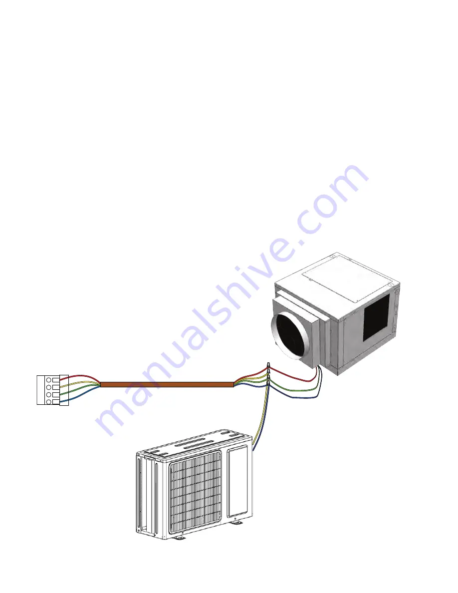
24V Wiring Connections (Evaporator)

1.

Route a standard 18-5 thermostat wire into the evaporator unit.

2.

Locate the wire thermostat connection cable inside of the evaporator unit.

3.

Connect the wires according to color ( red to red, green to green, and blue to blue). Note: The evaporator unit will not

contain a yellow wire. See next step for more information on Yellow wire.

4.

Connect one wire from the 18-5 thermostat wire to the low-voltage yellow wire (1). Then connect the other 18-5 wire to

the blue low-voltage wires (2). The other three wires will not be used.

Thermostat Wiring Connections 

Follow the thermostat installation instructions. 

NOTE: 

The white wire 

will not be used, as there is no heating function. 

NOTE: 

To ensure correct system operation, the 24V thermostat must be 

placed inside the wine cellar, preferably in a central location away from 

any airflow.        


R/RC

Y

G

C

Thermostat

Evaporator Unit

 Condensing Unit

Page 22 

08/09/21

Summary of Contents for MAGNUM H.E.

Page 1: ...MAGNUM H E OWNER S MANUAL NOTICE To activate the split system warranty the installing certified H AC R service tech must complete the split system warranty checklist and send back to CellarCool...

Page 2: ...not responsible for printing or clerical errors CellarCool reserves the right to make corrections or improvements to the information provided and to the related hardware at any time without notice Vi...

Page 3: ...ary Troubleshooting Guide Maintenance Schedule Page 2 Page 3 Page 4 Receiving Inspecting The System Page 6 Page 7 Condensate Drain Pan Page 8 Page 9 Rear Blower Orientation Instructions Page 10 Top Bl...

Page 4: ...zed refrigeration system designed for one purpose only to maintain the optimal temperature and humidity levels conducive to the proper storage and aging of fine wine This system produces minimal in ce...

Page 5: ...ou are REQUIRED to install a drain line to remove condensation from the evaporator unit 5 The warranty is not active until a warranty checklist has been received reviewed and approved 6 The system is...

Page 6: ...he insulation is to conducting heat and the more consistent your wine cellar s temperature will be Using higher R values in insulation will lower your operating costs and unit run time R 13 is the rec...

Page 7: ...eat away from the condensing unit is critical to the unit s performance and cannot be overstated As the system operates and cools a greater amount of heat is generated on the condensing side of the sy...

Page 8: ...Magnum 12000 H E condensing unit depending on unit ordered 3 Verify that the square to round plenum box contains the following 1 Square to round plenum 8 10 16 x 1 2 steeldrillingscrews Pictured 9000...

Page 9: ...t options Power supply knockout Bottle probe knockout Drain port 3 4 CPVC Interchangeable panels Display knockout Return air Supply air Line set knockout options Power supply knockout Display knockout...

Page 10: ...N PAN Check local codes and regulations regarding the disposal of condensation for specific installation requirements A separate drain line will need to be installed Please see page 26 for more info P...

Page 11: ...t for the flexible duct to prevent sags and bends Magnum 9000 and 12000 duct size 14 supply and return Register size 14 x 14 Filter size 14 x 14 MERV 4 Stretch out the duct to make a smoother interior...

Page 12: ...upply panel oriented to the right If this is your desired orientation proceed to the installation instructions on page 23 2 To reorient the blower first remove the access panels on the rear and top of...

Page 13: ...tate the blower to the rear configuration 4 Remove the six 6 screws securing the supply panel to the unit housing 5 Remove the supply panel REAR BLOWER ORIENTATION INSTRUCTIONS CONTINUED Page 11 08 09...

Page 14: ...re blower to supply panel using the eight 8 screws removed earlier 9 Reattach top panel with the six 6 screws removed earlier Attach the panel which was formerly the rear panel on the right side of th...

Page 15: ...top of the unit use the secondary foam fan bracket packaged with the unit pictured below The purpose of this piece of foam is to enable you to orient the blower so that the supply air duct faces upwar...

Page 16: ...the eight 8 screws securing the blower to the supply panel 3 Remove the six 6 screws securing the supply panel to the unit housing TOP BLOWER ORIENTATION INSTRUCTIONS CONTINUED 4 Remove the panel Pag...

Page 17: ...blower out through the rear access panel 6 Set the piece of foam shown on page 16 into the foam fan bracket on the bottom of the unit housing TOP BLOWER ORIENTATION INSTRUCTIONS CONTINUED Page 15 08...

Page 18: ...in from the rear and set upright on the piece of foam NOTE Make sure that the blower motor is closest to the side access panel as shown above TOP BLOWER ORIENTATION INSTRUCTIONS CONTINUED BLOWER MOTO...

Page 19: ...ews removed earlier 9 Attach the supply panel to the top of the unit using the six 6 screws removed earlier Then attach the blower to the panel using the eight 8 screws removed earlier TOP BLOWER ORIE...

Page 20: ...e double sided tape on the flanges of the square to round plenum 2 Stick the plenum onto the supply panel NOTE Make sure that the corners of the square to round plenum do not block the airflow from th...

Page 21: ...SQUARE TO ROUND PLENUM INSTALLATION CONTINUED 3 Secure the square to round plenum to the housing with the provided 10 16 x 1 2 steel drilling screws 4 Seal all seams with foil tape Page 19 08 09 21...

Page 22: ...nough to extend from the ceiling joists to the screws located at the top corners of the evaporator unit s e l o h w e r c s e h t t u o g n i p p i r t s t n e v e r p o t e u q r o t f o s b l 8 o t...

Page 23: ...stallation location 3 Route the bottle probe cable from the desired thermostat bottle location to the evaporator installation location 4 Route the drain line from a proper discharge location to the ev...

Page 24: ...able inside of the evaporator unit 3 Connect the wires according to color red to red green to green and blue to blue Note The evaporator unit will not contain a yellow wire See next step for more info...

Page 25: ...to the unit as shown in Figure 1 INSTALLING THE EVAPORATOR UNIT 12 Connect the end of the display cable labeled UNIT to the wire labeled UNIT coming from the controller box 13 Install the supplied pie...

Page 26: ...er or deburring tool remove all burrs from the cut section of the pipe F F Oblique Rough Warped 90 CONNECTING THE LINESET 3 Flare pipe ends Proper flaring is essential to achieve an airtight seal a Af...

Page 27: ...Using a spanner grip the nut on the unit tubing PIPING EXTENSION BEYOND FLARE FORM Outer Diameter of Pipe in A in Min Max 1 4 0 0275 0 05 3 8 0 04 0 063 0 04 0 07 0 078 0 086 0 078 0 094 Flare form P...

Page 28: ...The Magnum evaporator unit accepts 3 4 CPVC tubing It is imperative that you use primer and glue to ensure there is a watertight seal between the tubing and all fittings All joints and connections sh...

Page 29: ...as not been changed to 5 The factory setting allows the unit to run even if the EA alarm is tripped The alarm will be corrected when the water level inside the drip pan decreases and the float switch...

Page 30: ...itting coming from the unit and the CPVC tube which will be connected to it Insert the a piece of CPVC tubing into the female fitting Route additional CPVC tubing to an appropriate discharge location...

Page 31: ...le off to the side of the unit in your wine cellar with the probe level 5 To ensure a consistent temperature place bottle probe approximately three 3 feet away from the air output and not in the flow...

Page 32: ...cket REMOTE DISPLAY INSTALLATION AND CONFIGURATION NOTE Cut hole in the location shown for routing the display cable Tools needed 5 16 drill bit 3 16 drill bit drywall saw level pencil What s included...

Page 33: ...he four 4 provided drywall anchors into the drywall then tap them in with a hammer until they are flush with the wall 3 Place bracket against wall aligning screw holes with drywall anchors Insert the...

Page 34: ...e labeled DISPLAY to the JST connector on the back of the display DIS PL AY JST connector NOTE Before you continue to Step 4 locate the area where the display will be mounted You may route the display...

Page 35: ...oss 4 Cut along the perforated lines When finished remove template from wall INSTALLING THE EVAPORATOR 1 Locate the desired installation location 2 If utilizing an external or secondary drip tray ensu...

Page 36: ...cking from the double sided tape on the flush mount bracket 6 Align magnets with previously drilled holes Make sure the cut out portion of the bracket circled below is on the bottom Press the bracket...

Page 37: ...ace the display on the flush mount bracket as shown attaching the back of the display panel to the magnets on the mounting bracket Make sure that the alignment tab on the back of the display panel sit...

Page 38: ...EVAPORATOR WIRING DIAGRAM KDT Page 36 08 09 21...

Page 39: ...EVAPORATOR WIRING DIAGRAM 24V Page 37 08 09 21...

Page 40: ...CONDENSING UNIT WIRING DIAGRAM Page 38 08 09 21...

Page 41: ...n the system is installed with the condensing unit at a higher elevation than the coil Reverse oil return bend Oil saving bend Suction Line Evaporator Coil Within 16 of height Downward slope pitched t...

Page 42: ...ems do not utilize a solenoid valve or low pressure switch which allows the system to run like a residential HVAC system A 24V communication cable must be ran between the condensing unit and the evapo...

Page 43: ...condensing unit per electrical code 2 Remove electrical cover plate from unit 3 Connect wiring for 24V contactor communication cable L1 L2 and Ground as identified by terminal block label 4 Leave the...

Page 44: ...combustible gas In a location that is exposed to large amounts of dust In a location exposed to a excessive amounts of salty air In a closet or small room Special Considerations For Cold Weather And...

Page 45: ...ut on the end of eachexpansion bolt 5 Thread expansion bolts through holes in mounting brackets put mounting brackets in position and hammer expansion bolts into the wall 6 Check that the mounting bra...

Page 46: ...ately 225 psi Open both high side and low side gauge manifold knobs SLOWLY at the same time to admit nitrogen into the system until the gauge manifold reads 225 psi then close gauge manifold knobs Let...

Page 47: ...e port if necessary to achieve recommended subcooling Check the superheat at suction service valve on the condensing unit Adjust the TXV until the superheat is between 10 25 F at the service valve Aft...

Page 48: ...equivalent Confirm that the control is displaying the correct temperature and that no alarms are present INSTALLING THE CONDENSING UNIT continued Finalizing the Installation Approximate Operating Pre...

Page 49: ...mpressor Once the contactor relay is de energized the controller must wait five minutes before re energizing the relay This prevents the compressor from repeatedly turning off and on If the unit is ca...

Page 50: ...safety feature that will prevent the condensing unit from cycling on and off within a short period of time During the anti short cycle the condensing unit will typically remain off for 5 7 minutes Se...

Page 51: ...ft 3 4 greater than 50 ft Drain Line 3 4 ID CPVC Installation Condensing unit can be installed up to 100 line feet from the evaporator unit Thermostat KDT Advanced digital display 50 ft cable liquid...

Page 52: ...sions Refrigerant R 134a Condensing Unit HP 1 5 HP Voltage Rating 120V 15 amp dedicated circuit required Weight lbs 96 84 Amps 9 37 Running Amp Line Set Liquid line 3 8 OD Suction line 5 8 OD less tha...

Page 53: ...and adjust parameters such as setpoint Fon FOF etc SET To change the setpoint press the SET button When SEt is displayed on the screen press the SET button once more Use the UP and DOWN ARROW buttons...

Page 54: ...undergoing an Anti Frost Cycle While the Anti Frost Cycle is running dEF will be displayed on the screen See System Operation page for further details FAN The evaporator fan is running ALARM The alarm...

Page 55: ...dead clock battery will not affect the operation of your cooling unit The following alarm codes will not be displayed on the home screen However the alarm icon will be displayed in the event of an ala...

Page 56: ...adjust this setting in the User Menu Fon fan on The fan on time is preset to zero minutes This keeps the relative humidity of the wine cellar at a stable level If however you wish to raise the relativ...

Page 57: ...mer Service at 1 800 343 9463 Cellar temperature is too warm Possible cause Solution The temperature of the room to which the unit is exhausting has ex ceeded 110 F Intake temperature needs to drop be...

Page 58: ...icon illuminated on the control the system is going through an Anti Frost Cycle No action is required 2 If the system is not maintaining the correct cellar temperature the evaporator coil may be dirty...

Page 59: ...rm water 3 Ensure the condensing unit is free of debris and dust 4 Have a certified HVAC R technician service the condensing unit and clean the condenser coil Annually 1 Inspect outdoor condenser for...

Page 60: ...and eye irritation They are harmful or fatal if ingested Wear protective gloves when handling pan tabs Wash thoroughly after handling If pan tabs make contact with eyes rinse cautiously with water for...

Page 61: ...ccessories to enhance and customize your wine cooling unit Condensate Pump Kit The condensate pump kit automatically removes water that drips out of the evaporator unit s drain line The pump is contro...

Page 62: ...ited Warranty If the Split Startup Checklist is approved Purchaser will be sent activation approval documents and will start receiving the benefits of the Limi ed Warranty throughout the warranty peri...

Page 63: ...le receipted invoice or serial number which is evidence that the Product is within the Limited Warranty Period must be presented by the End User to CellarCool in order to obtain limited warranty servi...

Page 64: ...arCool Customer Service to arrange for replacement under the warranty guidelines When a claim for warranty is submitted for a condenser skid the End User must purchase a new condenser skid from Cellar...

Page 65: ...umentation to the customer to substantiate the finding This will include the Invoice from the Independent Certified H AC R Technician and the written report of the finding The Owner will become respon...

Page 66: ...available Monday through Friday from 6 30 a m to 4 00 p m PST The Customer Service representative will be able to assist you with your questions and warranty information more effectively if you provid...

Page 67: ...CellarCool 1738 E Alpine Ave Stockton CA 95205 1 800 343 9463 www cellarcool com...

Reviews: