background image

22

The SynScan™ AZ System

The AZ GOTO MODE provides extensive computerized GO-TO function to assist you in finding and enjoying the treasures of the night 
sky, such as planets, nebulae, star clusters, galaxies and much more. The hand control allows you to point your telescope to a specific object 
or even tour the skies at the touch of a button. The user-friendly menu system allows automatic slewing to over 42,900 objects. Even a 
beginning amateur astronomer can master its variety of features in a few observing sessions.

The SynScan AZ Hand Control

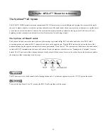
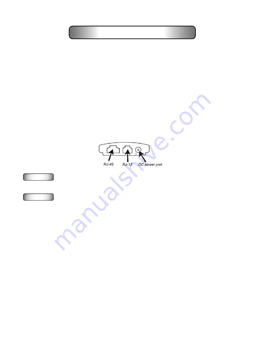
The SynScan AZ hand control has three ports on its bottom edge as pictured in 

Fig. 35

.  The hand control cable has a RJ-45 with 8 

connecting pins on one end and a RJ-12 connector with 6 pins on the opposite end.  Plug the RJ-45 end into the port on the base of the 
hand control and plug the opposite end into the drive base port marked “Hand Control.”  The center port on the bottom of the hand control 
is used for RS-232 communications between the SynScan AZ and a computer or other device (see “Linking with a Computer” for more 
details). The DC power port allows independent use of the SynScan AZ hand control for users who wish to browse the database or update 
the firmware without connecting to the telescope.


Fig. 35

The DC power port is for hand control stand-alone application only.  For telescope application, use the 12V DC port on the mount.

WARNING

WARNING

To connect the SynScan AZ to a PC, use only the RS-232 cable provided with the mount.

Using the AllView™ Mount for Astronomy

Summary of Contents for AllView Mount

Page 1: ...Multi Purpose Computerized Mount Instruction Manual...

Page 2: ...t Panoramic Control Easy Pano Mode Preset Pano Mode Time Lapse Mode Configuration Menu Slew to Home Video Coursing Using the AllView Mount for Astronomy The SynScan AZ System The SynScan AZ Hand Contr...

Page 3: ...e Appendix A RS 232 Connection Additional RS 232 Commands Sending a track rate through RS 232 to the hand control Sending a slow Goto command through RS 232 to the hand control Resetting the position...

Page 4: ...miliar with your mount so keep this manual handy until you have fully mastered your mount s operation This manual provides detailed information regarding each step as well as needed reference material...

Page 5: ...er to save all of the containers so that they can be used to transport or store the mount Tripod and Mount Setup The AllView mount is shipped with the tripod already attached To set up the mount and t...

Page 6: ...holder by sliding it into the accessory tray notch as shown in Fig 4 Push until it locks in place Assembling and Installing the Mounting Bracket The mounting bracket assembly includes four components...

Page 7: ...l b back and forth to find a suitable position for the camera you are attaching Tighten the hand screw on the Landscape Mounting Plate c to secure it in place 4 Loosen the altitude clutch knob on the...

Page 8: ...damage to the screw or camera body Fig 10 Fig 11 7 The camera position may be adjusted in 3 dimensions on the mounting bracket as shown in Fig 12 by a Up and down Z axis adjust the Dovetail Bar in the...

Page 9: ...Mounting Plate d1 and the Dovetail Bar Clamp d2 To separate them loosen the hand screw as shown in Fig 13 and Fig 14 Fig 13 Fig 14 Fig 15 Fig 16 2 Slide the Mounting Plate d1 and the Dovetail Bar Cla...

Page 10: ...18 and Fig 19 6 Loosen the altitude clutch knob located on the AllView mount s fork arm and turn the altitude axis so that the dovetail holder in parallel to the ground Retighten the clutch knob Note...

Page 11: ...unt should now look like Fig 20 and Fig 21 Fig 20 Fig 21 8 The camera s position may be adjusted in 3 dimensions on the Portrait Mounting Bracket as shown in Fig 22 a Forward and backward X axis adjus...

Page 12: ...cribed below When using a camera for panoramic photography a video camera for video coursing or a compact short tube telescope with the fork arm in the inner configuration the fork arm should be at yo...

Page 13: ...base of the fork arm rotate the fork arm 180 until it stops and tighten the set screw as shown in Fig 26 through Fig 29 Note When a camera or telescope optical tube is attached with the fork arm on t...

Page 14: ...nds Powering the AllView Mount The AllView mount requires 12 Volts DC nominal but it can use 8 16 Volts Never use a power supply that varies beyond this range or damage to the electronics may occur An...

Page 15: ...er on The firmware version will display on the LCD screen as shown in Fig 31 3 Press ENTER the hand control will prompt you to select one of the operating modes as shown in Fig 32 Use the scroll keys...

Page 16: ...and perform the measurement again press 1 The hand control will show both values and save the field of view information for future use 6 The hand control will display Step 2 HOME Position and will in...

Page 17: ...mera The actual shutter speed and aperture adjustments should be made on the camera itself The mount does not control this By pressing the 2 key you will be shooting the exposures manually The mount w...

Page 18: ...sed The second line shows the number of images to be taken in one full 360 rotation of the mount at the altitude angle displayed In the example in Fig 34 you are viewing layer 2 out of 5 total layers...

Page 19: ...the electronics shutter release cable to the camera to automatically release the shutter for each shot in the panorama The mount will slew to its proper picturing position take the image and move to t...

Page 20: ...this 6 The display will prompt you to enter the number of pictures you want to take during the pan from the starting point to the ending point of the slew You can choose any number up to 65 535 images...

Page 21: ...from one point to another The user does not need to calculate the speed in either axis of the mount Instead you specify the starting and ending points and the amount of time you wish to take to slew...

Page 22: ...RJ 45 with 8 connecting pins on one end and a RJ 12 connector with 6 pins on the opposite end Plug the RJ 45 end into the port on the base of the hand control and plug the opposite end into the drive...

Page 23: ...or to go back a level in the menu tree SETUP key is a quick hot key that takes you to the Setup submenu ENTER key is used to select the functions and submenu in the menu tree and to confirm certain f...

Page 24: ...e sure the mount is level to the ground There is a bubble level built into the base to help level the mount 2 Point the telescope roughly to the brightest star in the sky seen by your naked eyes 3 Mak...

Page 25: ...d automatically If you used the Edit Coordinates option in the step above the hand control will now ask you to Set Time Zone You can use the up and down scroll keys to select one of the two following...

Page 26: ...ect Brightest Star alignment using the scroll keys and press ENTER to confirm 2 Locate the brightest star in the sky that is far away from other bright stars Point the telescope roughly to the star yo...

Page 27: ...your eyepiece adjusting the rate of the slew motors as needed Press ENTER to complete the alignment If you see multiple stars in the eyepiece s field of view your alignment star will be the brightest...

Page 28: ...moved to a home position park the telescope before turning off the power The telescope setup including the mount has not been moved Changing the accessories is acceptable as long as it is done with gr...

Page 29: ...e view and press ENTER The SynScan AZ will record the amount of correction required and will recalculate its model of the sky The pointing accuracy in this particular part of the sky should be greatly...

Page 30: ...shortcut keys give you access to the most popular celestial catalogues to date Each catalog has a set number of objects to choose from Use the numeric keys to select an object by entering its catalog...

Page 31: ...real time plus hardware firmware and database versions of the SynScan hand control If the hand control is connected to the mount the menu will also display the firmware version of the motor control bo...

Page 32: ...00 0 degree 0 arc min and 0 arc second Use the numeric keys to enter the desired value and press the RIGHT directional key to move the cursor to the next digit First set the value for the azimuth axis...

Page 33: ...nd control will display a User Object number as shown in Fig 45 Use the scroll keys to change to the number you wish to represent your new user object and press ENTER The User Object number displayed...

Page 34: ...ject is below the horizon the hand control will display the Below Horizon warning and automatically return to the Recall Object menu Identify an Unknown Object SynScan AZ has the ability to identify a...

Page 35: ...nder full control of your computer once the connection is successfully established Do not use an RS 232 cable other than the one provided to connect between the hand control and your computer or damag...

Page 36: ...s software once Once it is saved on your computer only the firmware data file is needed for future updates 3 Download and save the firmware data file named SynScanVnnnnAZ ssf to the SynScan folder The...

Page 37: ...e Make sure the cables and connections are all in good working condition Close all applications that may be occupying the RS 232 port and try again Help If you receive the error message Firmware updat...

Page 38: ...ar Align Auto Select Sort by Backlash Tracking Sidereal Rate Lunar Rate Solar Rate Stop Tracking Set Slew Limits Handset Setting Factory Setting Panoramic Func Easy Pano Mode Preset Pano Mode Configur...

Page 39: ...e PAE Clear PAE Data GPS PC Direct Mode Object Catalog Named Star Solar System Mercury Venus Mars Jupiter Saturn Uranus Neptune Pluto Moon NGC Catalog IC Catalog Messier Catalog Caldwell Catalog SAO C...

Page 40: ...lew limits there will be no action Goto Ra Dec R34AB 12CE Scope must be aligned If command conflicts with slew limits there will be no action Get Azm Alt Z 12AB 4000 10 characters returned 12AB Azm co...

Page 41: ...hByte TrackRateLowByte 0 0 4 The number 35 is returned from the hand control Sending a slow Goto command through RS232 to the hand control 1 Convert the angle position to a 24 bit number Example if th...

Page 42: ...42 Appendix B Standard Time Zones of the World...

Page 43: ...t the interference by one or more of the following measures Reorient or relocate the receiving antenna Increase the separation between the equipment and receiver Connect the equipment into an outlet o...

Page 44: ...a Gedruckt in China Fabbricato in Cina This product contains a chemical s known to the State of California to cause cancer birth defects or other reproductive harm 2012 Celestron www celestron com All...

Reviews: