________
6
________
SP
D
F
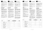
PERFORMANCES
LEISTUNGEN
PRESTACIONES
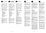
Le CELECTIC fonctionne avec les
chaudières suivantes :
CELTIC 2.30 Rsc b
CELTIC 2.20 Rsc b
CELTIC 2.23 HPS
CELTIC 2.20 FF Rsc b
CELTIC 2.23 FF HPS
CELTIC 2.20 Turbo HPS
CELTIC 2.24 Rsc b
SIAM CF
SIAM FF
GM 2.20 Rsc b
NECTRA
Der CELECTIC Boiler funktionniert mit
folgenden Kesseln :
NEWTECH 2.20 FF
NEWTECH 2.20
NEWTECH 2.24
NEWTECH 2.20 HPS
SIAM CF
SIAM FF
GM 13.20 Rsc b
El CELECTIC funciona con las siguientes
calderas :
CELTIC 18.23 RSc E
CELTIC 2.20 RSc E
CELTIC 2.20 FF RSc E
CELTIC 2.30 RSc E
CELTIC 2.23 HPS
CELTIC 2.23 FF HPS
SIAM CF
SIAM FF
Tableau donné pour une chaudière de 23 kW*
Diese tabelle betrifft einen 23 kW Heizkessel*
Cuadro indicativo para una caldera di 23 kW*
80 l
100 l
150 l
Durée de chauffe 15 à 60° C (min)
Aufheizdauer 15 bis 60° C (min)
Duración de calentamiento 15 a 60° C (min)
25
30
40
Débit spécifique l/min
Spezifische Durehflußmenge l/min
Caudal específico l/min
17
17,6
20,9
Consommation d’entretien KWh/24 h
Normalverbrauch KWh/24 h
Consumo de mantenimiento KWh/24 h
1,58
1,63
1,94
Constante de refroidissement
Erkältungskonstante
Constante de enfriamiento
0,493
0,408
0,323
Classe de protection électrique
Elektrischer Schutzwert
Clase de protección eléctrica
IPX4
IPX4
IPX4
* Les valeurs du tableau sont établies pour un ballon raccordé par le haut et placé sous la chaudière.
* Diese angaben wurden für einen unter dem Kessel stehenden Boiler mit Obenanschluß aufgestellt.
* Los valores del cuadro han sido establecidos para un acumulador empalmado por arriba.
Il est recommandé de placer le ballon
aussi près que possible de la chaudière
afin de ne pas faire chuter les
performances du système du fait des
pertes de charge et des pertes thermiques
dans les tuyauteries.
Cependant une longueur équivalente à 20
m de tuyauterie 16 x 18 est possible (ce
qui correspond à 10 m aller/retour) sans
tenir compte des accidents de parcours
qui sont à déduire de cette longueur
maximum.
Il est nécessaire de calorifuger les tuyaux
de raccordement.
Le ballon peut être placé n’importe où
(placard, cuisine, cave…) sous réserve
que les instructions de montage soient
respectées.
Wir raten den Durchlauferhitzer so nah
wie möglich neben dem Kessel
anzubringen, um zu verhindern, daß die
Leistungen des Systems durch last-und
Wärmeverluste in den Leitungen
herabgesetzt werden.
Es ist jedoch möglich ein 20 m langes
Rohr (16 x 18) zu benützen, das heißt 10
m hin und zurück, ohne Berücksichtigung
verschiedener Hindernisse, die von der
maximalen Gesamtlänge abzuziehen sind.
Darüber hinaus ist es notwending, die
Anschlußrohre zu isolieren.
Der boiler kann an jedem beliebigen Ort
aufgestellt werden (schrank, küche, keller
usw...) unter Berücksichtigung der hier
angegebenen Montageanweisungen.
Se recomienda colocar el acumulador lo
más cerca posible de la caldera, con el fín
de no disminuir las prestaciones de este
sistema, debido a las pérdidas de carga y
a las pérdidas térmicas en las tuberías.
No obstante puede cololarse una tubería
16x18, de una longitud equivalente a 20
m, lo que corresponde a 10 m ida y
vuelta, sin tener en cuenta los accesorios
del circuito que deben dedurcirse de esta
longitud máxima.
Es necesario calorifugar las tuberfas de
empalme.
El acumulador puede estar colocado en
cualquier sitio (armario, cocina, sótano,…)
siempre y cuando se respeten las
instrucciones de montaje.
________
15
________
NL
I
GB
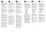
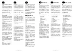
COMMISIONING
MESSA IN
FUNZIONE
INDIENSTSTELLING
1
– Turn the summer and winter switch to
the midway off position on the boiler, to
ensure that the appliance does not come
into operation during the filling period.
2
– To fill the system, open the cold water
inlet valve on the boiler. Open one of the
hot water outlets on the installation
preferably the furthest from the cylinder.
Check for any leaks and re-make and
tighten connections as necessary.
3
– It is essential that the cylinder and
pipework are flushed to ensure safe and
correct operation. Open the remaining hot
water outlets and allow the water to flow
for approximately two minutes. This will
ensure that all the air is purged from the
circuits and any remaining debris is
removed.
4
– Purge the pump.
An isolating switch is incorporated within
the electrical control box to allow the
Celectic to be turned off whilst leaving the
boiler fully operational.
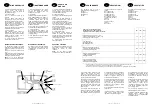
Electrical connections
The Celectic requires a 240 volt 50 Hz
single phase supply and must be
connected as shown in the diagram on
page 10 (flexible cable not supplied).
Both the Celectic and the combination
boiler must be earthed.
An isolating switch is incorporated within
the electrical control box to allow the
Celectic to be turned off whilst leaving the
boiler fully operational.
NOTA
: There are no electrical connections
between the boiler and the cylinder.
1
– Posizionare l’interruttore della caldaia
in posizione “arresto” al fine di evitare
l’avviamento in fase di riempimento e di
spurgo.
2
– Riempire lo scaldabagno.
Aprire il rubinetto dell’acqua fredda della
caldaia.
Aprire un rubinetto d’acqua calda
dell’impianto per spurgare l’aria e mettere
il gruppo in posizione.
« Alimentazione » .
Per accelerare il riempimento é possibile
aprire il by-pass (fig. B, rif. 11) a mezzo
del bottone fresato (Per l’apertura svitare.
Per la chiusara : avvitare).
3
– Sciacquare il serbatoio
Questa operazione permette di assicurare
la pulizia dell’apparecchio. Per fare ció,
lasciar scorrere l’acqua, dopo il
riempimento, per qualche minuto. Ció ha il
vantaggio di spurgare il circuito.
4
– Spurgare la pompa allentando il tappo
del propulsore di quest’ultima.
Collegamento elettrico
Il collegamento elettrico del serbatoio si
effectua tramite un cavo a 3 conduttori
(fase, neutro e terra) non fornito.
Questo deve essere collegato sulla
morsettiere come indicato in figura.
L’interruttore dello scaldabagno serve
solamente a togliere la funzione acqua
calda sanitaria ma non arresta la funzione
acqua calda sanitaria ma non arresta la
funzione riscaldamento.
NOTA
: Non c’è nessun collegamento
elettrico tra la caldaia e il serbatoio.
1
– De schakelaar van de ketel op stand
“Stop” zetten teneinde deze te beletten te
starten tijdens de vulling en ontluchting.
2
– De boiler vullen
Open de koudwaterkraan van de
wandketel.
Open een warmwaterkraan van de
installatie om te ontluchten en plaats de
groep op de stand “voeding”. Teneinde de
vulling te versnellen, kunt U de by pass
openen (fig. B rep 11), met behulp van
een gekartelde knop (opening door los te
vijzen, sluiting door vast te vijzen).
3
– De boiler spoelen
Dit laat toe het toestel te reinigen. Het
water laten weglopen gedurende enkele
minuten na de vulling. Dit heeft het
voordeel het circuit te ontluchten.
4
– De pomp ontluchten door de stop van
de pompstarter los te vijzen.
Elektrische aansluitingen
De elektrische aansluiting van de boiler
uitvoeren door middel van een kabel met 3
geleiders (F, N aarding) niet meegeleverd.
Deze wordt aangesloten op de aansluit-
klemmen volgens schema.
De schakelaar van de boiler dient alleen
om de produktie van sanitair warm water
te stoppen zonder de verwarmingsfunktie
te stoppen.
NOTA
: Er is geen enkele elektrische
aansluiting tussen de ketel en de boiler.
N
P
Thermostat
Termostato
Thermostaat
Terminal
Morsettiera
Aansluitklem
Earth
Terra
Aarding
Neutral
Nautro
Neutraal
220V mono ~ 50Hz
Live
Fase
Fase
Fuse
Fusibile
Zekering
Switch with indicator light
Interruttore con spia
Schakelaar met lampje
________
6
________
SP
D
F
PERFORMANCES
LEISTUNGEN
PRESTACIONES
Le CELECTIC fonctionne avec les
chaudières suivantes :
CELTIC 2.30 Rsc b
CELTIC 2.20 Rsc b
CELTIC 2.23 HPS
CELTIC 2.20 FF Rsc b
CELTIC 2.23 FF HPS
CELTIC 2.20 Turbo HPS
CELTIC 2.24 Rsc b
SIAM CF
SIAM FF
GM 2.20 Rsc b
NECTRA
Der CELECTIC Boiler funktionniert mit
folgenden Kesseln :
NEWTECH 2.20 FF
NEWTECH 2.20
NEWTECH 2.24
NEWTECH 2.20 HPS
SIAM CF
SIAM FF
GM 13.20 Rsc b
El CELECTIC funciona con las siguientes
calderas :
CELTIC 18.23 RSc E
CELTIC 2.20 RSc E
CELTIC 2.20 FF RSc E
CELTIC 2.30 RSc E
CELTIC 2.23 HPS
CELTIC 2.23 FF HPS
SIAM CF
SIAM FF
Tableau donné pour une chaudière de 23 kW*
Diese tabelle betrifft einen 23 kW Heizkessel*
Cuadro indicativo para una caldera di 23 kW*
80 l
100 l
150 l
Durée de chauffe 15 à 60° C (min)
Aufheizdauer 15 bis 60° C (min)
Duración de calentamiento 15 a 60° C (min)
25
30
40
Débit spécifique l/min
Spezifische Durehflußmenge l/min
Caudal específico l/min
17
17,6
20,9
Consommation d’entretien KWh/24 h
Normalverbrauch KWh/24 h
Consumo de mantenimiento KWh/24 h
1,58
1,63
1,94
Constante de refroidissement
Erkältungskonstante
Constante de enfriamiento
0,493
0,408
0,323
Classe de protection électrique
Elektrischer Schutzwert
Clase de protección eléctrica
IPX4
IPX4
IPX4
* Les valeurs du tableau sont établies pour un ballon raccordé par le haut et placé sous la chaudière.
* Diese angaben wurden für einen unter dem Kessel stehenden Boiler mit Obenanschluß aufgestellt.
* Los valores del cuadro han sido establecidos para un acumulador empalmado por arriba.
Il est recommandé de placer le ballon
aussi près que possible de la chaudière
afin de ne pas faire chuter les
performances du système du fait des
pertes de charge et des pertes thermiques
dans les tuyauteries.
Cependant une longueur équivalente à 20
m de tuyauterie 16 x 18 est possible (ce
qui correspond à 10 m aller/retour) sans
tenir compte des accidents de parcours
qui sont à déduire de cette longueur
maximum.
Il est nécessaire de calorifuger les tuyaux
de raccordement.
Le ballon peut être placé n’importe où
(placard, cuisine, cave…) sous réserve
que les instructions de montage soient
respectées.
Wir raten den Durchlauferhitzer so nah
wie möglich neben dem Kessel
anzubringen, um zu verhindern, daß die
Leistungen des Systems durch last-und
Wärmeverluste in den Leitungen
herabgesetzt werden.
Es ist jedoch möglich ein 20 m langes
Rohr (16 x 18) zu benützen, das heißt 10
m hin und zurück, ohne Berücksichtigung
verschiedener Hindernisse, die von der
maximalen Gesamtlänge abzuziehen sind.
Darüber hinaus ist es notwending, die
Anschlußrohre zu isolieren.
Der boiler kann an jedem beliebigen Ort
aufgestellt werden (schrank, küche, keller
usw...) unter Berücksichtigung der hier
angegebenen Montageanweisungen.
Se recomienda colocar el acumulador lo
más cerca posible de la caldera, con el fín
de no disminuir las prestaciones de este
sistema, debido a las pérdidas de carga y
a las pérdidas térmicas en las tuberías.
No obstante puede cololarse una tubería
16x18, de una longitud equivalente a 20
m, lo que corresponde a 10 m ida y
vuelta, sin tener en cuenta los accesorios
del circuito que deben dedurcirse de esta
longitud máxima.
Es necesario calorifugar las tuberfas de
empalme.
El acumulador puede estar colocado en
cualquier sitio (armario, cocina, sótano,…)
siempre y cuando se respeten las
instrucciones de montaje.
________
15
________
NL
I
GB
COMMISIONING
MESSA IN
FUNZIONE
INDIENSTSTELLING
1
– Turn the summer and winter switch to
the midway off position on the boiler, to
ensure that the appliance does not come
into operation during the filling period.
2
– To fill the system, open the cold water
inlet valve on the boiler. Open one of the
hot water outlets on the installation
preferably the furthest from the cylinder.
Check for any leaks and re-make and
tighten connections as necessary.
3
– It is essential that the cylinder and
pipework are flushed to ensure safe and
correct operation. Open the remaining hot
water outlets and allow the water to flow
for approximately two minutes. This will
ensure that all the air is purged from the
circuits and any remaining debris is
removed.
4
– Purge the pump.
An isolating switch is incorporated within
the electrical control box to allow the
Celectic to be turned off whilst leaving the
boiler fully operational.
Electrical connections
The Celectic requires a 240 volt 50 Hz
single phase supply and must be
connected as shown in the diagram on
page 10 (flexible cable not supplied).
Both the Celectic and the combination
boiler must be earthed.
An isolating switch is incorporated within
the electrical control box to allow the
Celectic to be turned off whilst leaving the
boiler fully operational.
NOTA
: There are no electrical connections
between the boiler and the cylinder.
1
– Posizionare l’interruttore della caldaia
in posizione “arresto” al fine di evitare
l’avviamento in fase di riempimento e di
spurgo.
2
– Riempire lo scaldabagno.
Aprire il rubinetto dell’acqua fredda della
caldaia.
Aprire un rubinetto d’acqua calda
dell’impianto per spurgare l’aria e mettere
il gruppo in posizione.
« Alimentazione » .
Per accelerare il riempimento é possibile
aprire il by-pass (fig. B, rif. 11) a mezzo
del bottone fresato (Per l’apertura svitare.
Per la chiusara : avvitare).
3
– Sciacquare il serbatoio
Questa operazione permette di assicurare
la pulizia dell’apparecchio. Per fare ció,
lasciar scorrere l’acqua, dopo il
riempimento, per qualche minuto. Ció ha il
vantaggio di spurgare il circuito.
4
– Spurgare la pompa allentando il tappo
del propulsore di quest’ultima.
Collegamento elettrico
Il collegamento elettrico del serbatoio si
effectua tramite un cavo a 3 conduttori
(fase, neutro e terra) non fornito.
Questo deve essere collegato sulla
morsettiere come indicato in figura.
L’interruttore dello scaldabagno serve
solamente a togliere la funzione acqua
calda sanitaria ma non arresta la funzione
acqua calda sanitaria ma non arresta la
funzione riscaldamento.
NOTA
: Non c’è nessun collegamento
elettrico tra la caldaia e il serbatoio.
1
– De schakelaar van de ketel op stand
“Stop” zetten teneinde deze te beletten te
starten tijdens de vulling en ontluchting.
2
– De boiler vullen
Open de koudwaterkraan van de
wandketel.
Open een warmwaterkraan van de
installatie om te ontluchten en plaats de
groep op de stand “voeding”. Teneinde de
vulling te versnellen, kunt U de by pass
openen (fig. B rep 11), met behulp van
een gekartelde knop (opening door los te
vijzen, sluiting door vast te vijzen).
3
– De boiler spoelen
Dit laat toe het toestel te reinigen. Het
water laten weglopen gedurende enkele
minuten na de vulling. Dit heeft het
voordeel het circuit te ontluchten.
4
– De pomp ontluchten door de stop van
de pompstarter los te vijzen.
Elektrische aansluitingen
De elektrische aansluiting van de boiler
uitvoeren door middel van een kabel met 3
geleiders (F, N aarding) niet meegeleverd.
Deze wordt aangesloten op de aansluit-
klemmen volgens schema.
De schakelaar van de boiler dient alleen
om de produktie van sanitair warm water
te stoppen zonder de verwarmingsfunktie
te stoppen.
NOTA
: Er is geen enkele elektrische
aansluiting tussen de ketel en de boiler.
N
P
Thermostat
Termostato
Thermostaat
Terminal
Morsettiera
Aansluitklem
Earth
Terra
Aarding
Neutral
Nautro
Neutraal
220V mono ~ 50Hz
Live
Fase
Fase
Fuse
Fusibile
Zekering
Switch with indicator light
Interruttore con spia
Schakelaar met lampje


