12
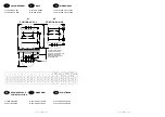
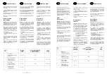
Cas de montage
raccordement vers le bas
Montage mit anschluss
nach unten
Caso de instalacion con
conexiones hacia abajo
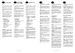
1 -
Démonter complètement le tube
X
.
2 -
Dévisser complètement les écrous
laiton
A
et
B
(ne pas dévisser les
manchons plastique, ils sont montés
avec de la pâte d'étanchéité).
3 -
Retourner l'ensemble pompe – tube
platine.
4 -
Remonter le tube
Y
(fourni en
accessoire) à la place du tube
X
.
5 -
Resserrer les écrous
A
et
B.
6 -
S'assurer que tous les joints sont bien
en place.
1 -
Das Rohr
X
vollständig ausbauen.
2 -
Die Messingmuttern
A
und
B
vollkommen aufschrauben (die
Kunststoffhülsen nicht aufschrauben,
sie sind mit einer Dichtungsmasse
montiert).
3 -
Umdrehen der Einheit Pumpe Rohr
Platte.
4 -
Einbau des Rohres
Y
(wird als
Zubehör geliefert) an Stelle des
Rohres
X
.
5 -
Festziehen der Muttern
A
und
B.
6 -
Überprüfen, o
balle Dichtungen
einwandfrei eingebaut sind.
1 -
Desmontar totalmente el tubo
X.
2 -
Destornillar completamente las
tuercas de latón
A
y
B
(no
destornillar los manguitos de plástico
pues están montados con masa de
estanqueidad).
3 -
Dar vuelta al conjunto bomba, tubo,
platina.
4 -
Volver a montar el tubo
Y
(incluido
como accesorio) en el lugar del tubo
X
.
5 -
Apretar las tuercas
A
y
B.
6 -
Asegurarse de que todas las juntas
estén en su sitio.
________
12
________
SP
D
F
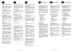
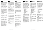
Cas de montage
raccordement vers le bas
1
– Démonter complètement le tube X.
2
– Dévisser complètement l’écrou
plastique
A
et l’écrou laiton
B
.
3
– Démonter le manchon plastique
isolant
C
.
4
– Remonter le manchon plastique
isolant
C
sur
D
(couple de serrage entre
15 et 20 Nm)
5
– Retourner l’ensemble pompe – tube
platine.
6
– Remonter le tube
Y
(fourni en
accessoire) à la place du tube
X
.
7
– S’assurer que tous les joints sont bien
en place.
Montage mit anschluss
nach unten
1
– Den Rohr X ganz demontieren.
2
– Muttern 1 und 4 lösen ohne
abzuschrauben, Muttern A und B
abschrauben.
3
– Den Satz Pumpe – Rohr – Platte
umdrehen.
4
– Diesen Satz wieder an den Boiler
montieren. Muttern 1 und 4 wieder
festschrauben.
5
– Den Rohr Y wieder montieren am
Platz X (als Zubehör liefern).
6
– Sich vergewissern, daß alle
Dichtungen festsitzen.
Caso de instalación con
conexiones hacia abajo
1
– Desmontar completamente el tubo X.
2
– Aflojar las tuercas 1 y 4 sin
desmontarlas y destornillar las tuercas A y
B.
3
– Dar la vuelta al conjunto bomba – tubo
– plantilla.
4
– Montar de nuevo el conjunto en la
cuba. Apretar las tuercas 1 y 4.
5
– Montar el tubo Y (proporcionado como
accesorio) en lugar del tubo X.
6
– Asegurarse de que todas las juntas
estén bien colocadas.
________
9
________
NL
I
GB
INSTALLATION
EXAMPLES
ESEMPI
DI MONTAGGIO
VOORBEELDEN
VAN AANSLUITING
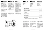
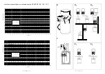
D1 Free standing cylinder
D2 Wall mounted cylinder
These models are all designed for vertical
mounting with top outlet connections.
However, it is possible to convert the
connections to bottom outlets by following
the instructions given on page 12.
Type of hot water outlet connections
E1
This installation shows the Celectic systems
with the hot water outlets being served by
the stored water from the cylinder
This type of installation is particularly
suitable where larger quantities oh hot
water are required, for example,
properties with more than one bathroom,
commercial installations with large sinks
etc.
E2
This installation is similar to E1, but with
the added facility of utilising the secondary
heat exchanger off the boiler to supply hot
water outlets where smaller quantities are
required during the day, without having to
heat the cylinder. For example,
diswashers, washing machines, hand
basins etc.
It is essential that a non-return valve is
fitted between the draw off connection to
the low demand outlets and the outlet
from the Celectic cylinder, to ensure that
water is not drawn from the cylinder.
D1 Serbatoio al suolo
D2 Serbatoio al muro
II presente scaldabagno é consegnato per
essere montato verticalmente, collegamenti
verso l’alto.
E tuttavia possibile montarlo verticalmente,
collegamenti verso il basso ; ciò necessita
un adattamento (vedi schema pag. 12).
Tipi di collegamenti idraulici
E1
Questo montaggio di base consente il
prelievo di ECS (acqua calda sanitaria),
esclusi-vamente attraverso lo scaldabagno.
Di conseguenza, dopo l’arresto dell’impianto,
bisogna attendere il riscaldamento dello
scaldabagno per disporre d’acqua calda
sanitaria
E2
Spillando una seconda volta l’acqua calda
sanitaria all’uscita della caldaia, si può
ottenere, su una parte definita dell’impianto,
acqua calda non transitante attraverso lo
scaldabagno. Di conseguenza, é possibile
disporre d’acqua calda in questi posti di
attingimento ad ogni momento.
E necessario aggiungere all’impianto una
valvola antiritorno fra lo spillo e lo
scaldabagno. Questa valvola deve essere
montata passando nel senso caldaia
verso scaldabagno.
D1 Boiler stand op de grond
D2 Boiler hangend aan de muur
Deze boiler wordt geleverd om vertikaal
gemonteerd te worden, aansluitingen naar
boven.
Het is evenwel mogelijk om hem vertikaal
aan te sluiten, aansluitingen naar
onderen, dit vraagt wel een aanpassing
(zie schema blz. 12).
Voorbeelden van hydraulische aanslui-
tingen
E1
Deze basismontage laat een aftapping
van het SWW toe door de boiler alleen.
Bijgevolg, na het stoppen van de
installatie, moet men de heropwarming
van de boiler afwachten om opnieuw over
sanitair warm water te beschikken.
E2
Door een tweede aftapping van SWW te
voorzien op de uitgang van de wandketel,
laat dit toe om op een gekozen gedeelte
van de installatie, het warm water niet
door de boiler te laten gaan.
Het is noodzakelijk om een antiterugslagklep
te voorzien op de installatie tussen het
aftappunt en de boiler. Deze klep moet
gemonteerd worden in de richting van de
wandketel naar de boiler.


