2.3.3. COMMUNICATIONS IN THE SERIAL BRIDGE MODE
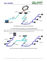
Communication in the serial bridge mode allows to transfer data via Ethernet network between serial port of the Servers ports in one-
to-one topology or one-to-many by the use of client and server TCP/UDP services.
2.3.4. COMMUNICATIONS IN THE INDUSTRIAL AUTOMATION MODE (Modbus Gateway)
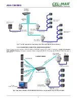
Communication in the MODBUS Gateway (IA) allows conversion of MODBUS-RTU master/slave protocol and MODBUS-ASCII
master/slave protocol to MODBUS-TCP protocol and inversely. It's let to integrate MODBUS-RTU/ASCII devices with MODBUS-TCP
devices in a single network.
2.3.5. OTHER COMMUNICATION TYPES
The ADA-13040MG converter can be configured in other communication types, like:
– terminal mode,
– modem emulation mode,
– console mode,
– user mode.
However, in the case of RS485/RS422 converter, it will not be able to work properly in these modes, as they relate to the full
RS232 interface.
3. INSTALLATION
This chapter will show how correctly connect ADA-13040MG to RS485/422 network, LAN/WAN network and power supply.
To reduce disturbance from environment, it is recommended to:
– use shielded twisted multipair type cables, which shield should be connected to the grounding on one end of the cable,
– lay signal cables at a distance not less than 25 cm from power cables,
– use suitable diameter cable for power supply on account of voltage drop,
– use the interference eliminators for powering the converters installed in the range of some building,
– not powering the converters form power-circuit of devices generate large impulse disturbance like contactors, relays,inverters.
3.1. ASSEMBLING
The ADA-13040MG converter case is adapted to assembly on TS-35 (DIN35) rail. To install the device on TS-35 should be the upper
part of the casing put hooks on the terminal and then press the bottom of the cover until you hear a characteristic "Click" sound.
3.2. ETHERNET NETWORK
The ADA-13040MG has to be connected to ETHERNET network by the use of the switch, the HUB or directly to the PC network
adapter.
The table below shows preparing of the straight cable for Converter connection to switch or hub.
Table 1. The straight cable.
RJ45 Pin
No.
Signal
Wire Color
EIA/TIA 568B
Straight cable
UTP 4x2x0,5
Wire Color
EIA/TIA 568B
Signal
RJ45 Pin
No.
1
TX+
White-Orange
2
TX-
Orange
3
RX+
White-Green
4
Not used
Blue
5
Not used
White-Blue
6
RX-
Green
7
Not used
White-Brown
8
Not used
Brown
White-Orange
TX+
1
Orange
TX-
2
White-Green
RX+
3
Blue
Not used
4
White-Blue
Not used
5
Green
RX-
6
White-Brown
Not used
7
Brown
Not used
8
The table below shows preparing of cross-over cable for Converter connection to PC network adapter or connections converters
together for functioning as point-to-point serial bridge.
Table 2. The cross-over cable.
RJ45 Pin
No.
Signal
Wire Color
EIA/TIA 568B
Cross-Over Cable
UTP 4x2x0,5
Wire Color
EIA/TIA 568B
Signal
RJ45 Pin
No.
1
TX+
White-Orange
2
TX-
Orange
3
RX+
White-Green
4
Not used
Blue
5
Not used
White-Blue
6
RX-
Green
7
Not used
White-Brown
8
Not used
Brown
White-Green
TX+
1
Green
TX-
2
White-Orange
RX+
3
Blue
Not used
4
White-Blue
Not used
5
Orange
RX-
6
White-Brown
Not used
7
Brown
Not used
8
6
ADA-13040MG


