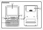
1. SETS
Total or remaining number of sets in selected
program. If SET is not displayed the bargraf illustrates
stimulation amplitude for left channel.
2. REPS
Total or remaining number of repetitions in each set.
If REP is not displayed, the bargraph illustrates
stimulation amplitude for right channel.
3. BROKEN CIRCUIT
Indicates if the circuit (connection between
stimulator and electrode) is broken.
For further information, see
Trouble Shooting.
4. PAUSE
The stimulation program is paused.
5. BATTERY STATUS
Empty batteries. This symbol is shown when the batter-
ies are almost empty.
6. PROGRAM NUMBER
Selected program number. See
Program Description for
further information.
7. LEVEL NUMBER
Intensity level. See
Program Description for further
information.
8. REMAINING TIME
Remaining program time in minutes and seconds.
Time is flashing during timer setting, also counts down
the time for break between sets.
9. BODY PART
Selected body part for stimulating, indicated by the
filled body part.
10. KEY LOCK
Key lock is activated.
11. WORK/REST
Upper part flashes during work, lower part during rest
periods.
12. AUTO STIMULATION MODE
Activated automatic amplitude setting.
“AUTO”
is flash-
ing during test mode and steady during stimulation.
13. AMPLITUDE LEVEL
Selected amplitude in mA (not shown in Auto stimula-
tion mode).
For information about the symbols on the stimulator’s back,
see section
Key to the Stimulator Symbols.
OVERVIEW – GET TO KNOW YOUR STIMULATOR
DISPLAY SYMBOLS
1.
2.
3.
3.
4.
5.
6.
11.
12.
13.
7.
8.
9.
10.
12.
13.
2526_CEFAR_MYO.ACTIV_X2__ENG_3-16 6
2006-07-07 11:09:57
Summary of Contents for activ X2
Page 14: ...195 2526_CEFAR_MYO ACTIV_X2_EP_195 2195 195 2006 07 07 11 49 39...
Page 15: ...196 2526_CEFAR_MYO ACTIV_X2_EP_195 2196 196 2006 07 07 11 49 40...
Page 16: ...197 2526_CEFAR_MYO ACTIV_X2_EP_195 2197 197 2006 07 07 11 49 41...
Page 17: ...198 2526_CEFAR_MYO ACTIV_X2_EP_195 2198 198 2006 07 07 11 49 42...


