


INSTALLATION
Always wear the appropriate protective apparel when working on
or around the pumping equipment. Safety glasses with side shields,
heavy work gloves (use insulated work gloves when handling hot
items), steel-toed shoes, hard hat, and any other protective gear as
needed for protection. One example of other gear would be breath-
ing apparatus when working near toxic materials. Use lifting
devices, manufactured expressly for the purpose of lifting, to move
the pumping machinery. Do not attempt to lift the assembly or its
components manually. Use only devices with lifting capabilities in
excess of the weight of the unit being lifted. Inspect straps, chains,
hooks, etc. for damage and lifting capability before use. Lift only at
the center of gravity.
Personal injury, death, and/or equipment damage could occur if
good lifting practices are not used.
APPLICATION AND REAPPLICATION
At the time of installation, the equipment received should have
already been selected for the service required. You must read the
paperwork for the installation and check the serial number of the
pump to assure that you are installing the correct pump into the ser-
vice for which it was selected.
Many pumps look identical from the outside but can be made of dif-
ferent materials and/or be constructed differently inside. Personal
injury, death, equipment damage, product (pumpage) damage,
and/or product loss could occur if the incorrect pump is installed.
Do not transfer an existing pump to any other service conditions until
you have thoroughly reviewed the pump construction, materials, siz-
ing, sealing, pressure containing capability, head/capacity capabili-
ty, and temperature capability with respect to the required service.
Consult your Dean Pump sales engineer with all the service require-
ments and a full description of the existing pump (including the serial
number), seal, and sub-systems so that we can assist you in a suc-
cessful reapplication.
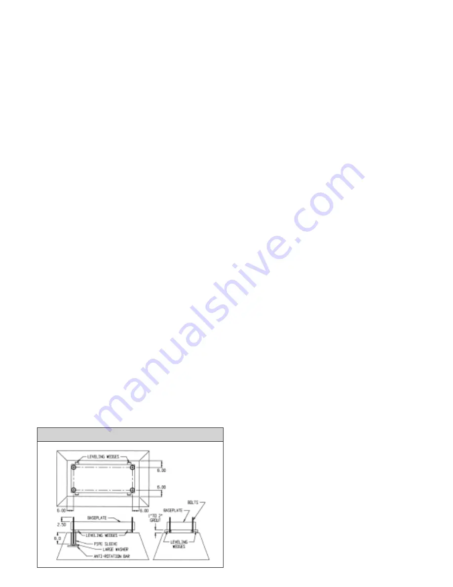
PUMP FOUNDATION
The pump foundation provides rigid support to the baseplate and
maintains the alignment of the pumping unit. Baseplates are
designed to rigidly support the pump and driver without vibration or
distortion only when they are properly set, leveled, and secured to
the foundation.
The purchaser may elect to mount the pump without grouting the
baseplate. In any case the baseplate must be fully supported by the
customer’s mounting means to prevent vibration and distortion.
BASEPLATE MOUNTING AND ALIGNMENT
The sequence of mounting which must be observed for proper base-
plate and pump mounting is:
1) Place baseplate, with pump and driver mounted thereon, on the
pump foundation.
2) Use wedges under the baseplate edges, at each foundation
bolt, to properly support and level the unit. Check this with a
spirit level. Pull down the baseplate mounting bolt nuts tightly
and recheck for level. Correct if necessary.
3) Align the driver to the pump. See
“Pump and Driver
Alignment’’
on page 4.
4) Grout the baseplate.
Do not grout the baseplate to the founda-
tion until the pump and driver are correctly aligned.
The
baseplates are provided with grouting holes. Fill the entire
void under the baseplate with grout and firmly embed the
baseplate edges.
5) Connect the suction and discharge piping without forcing the
piping into position. See
“Suction and Discharge Piping’’
on
page 4. The pipe flanges must line up with the pump flanges
“
freely
”.
Install a
“
new
”
bolt, of the correct size per ASME/ANSI
B16.5 and the correct material per ASME/ANSI B16.5, in
every bolt hole. Tighten all bolts evenly. Use only new
uncorroded fasteners.
WARNING:
Strain caused by “forcing”, improper flange bolting, and/or
misalignment may cause failure of the pumping unit, flanges, piping
and/or fluid (pumpage) release which could cause personal injury,
death, and/or damage to this and/or other equipment.
6) Recheck pump and driver alignment to ensure that no distortion
of the pump unit has been caused by piping strain. Correct
piping if misalignment has occurred and again align pump and
driver.
7) Connect all other (auxiliary) piping necessary for safe and
successful operation of the equipment in the specific service
conditions of the application. See
“Pump Cooling
Requirements”
on page 6.
WARNING:
Make sure that all piping is installed into its correct connection.
Installation of a pipe into an incorrect location could result in an
explosion and personal injury or death as well as damage to this
and/or other equipment. Install pressure relief valves in any cavities
that could be subjected to pressures in excess of the allowable work-
ing pressure. Explosion, personal injury, death, and/or damage to
this and/or other equipment may occur if pressure exceeds allow-
able.
One example of the above would be the cooling jacket around the
seal chamber. If this chamber were full of water and someone
would close both the inlet and outlet valves and then operate the
pump at 500 degrees fahrenheit, the vapor pressure of the water,
665 PSIG, would far exceed the capacity of the jacket and possibly
other parts. In this example, a relief valve must be installed between
the pump and the outlet valve.
8) Recheck the alignment between the driver (motor,
turbine, or engine) and pump shafts. Installation of piping
3
T
YPICAL
F
OUNDATION
L
AYOUT


