


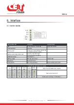


9.2 Controller - Inview S Slot
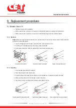
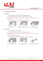
9.2.1 Removal
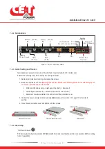
1. Insert a soft edged pin into the hole to unlock the latch. (Hole diameter is 3 mm)
2. Gently push and press down the pin to unlock the latch and then remove the controller.
Warning: while removing the controller from the shelf, hold the top and bottom part of front plastic. Do not press on the
touch screen.
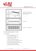
3. Remove the controller from shelf and replace with a new unit or dummy cover.
Push and press down the pin, and pull the unit
Remove the module from shelf
Insert the pin into the hole
Pin
Hole
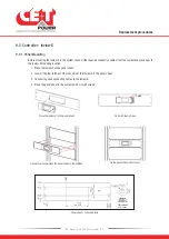
9.2.2 Inserting
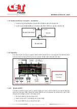
1. Place the Inview S Slot and slide into the shelf.
2. Push the unit firmly until the controller rear part is engaged correctly with shelf.
Warning: while inserting the controller into the shelf, push on the left side (ETH and USB port) of the controller. Do not
press on the touch screen.
3. Make sure the latch is locked in the shelf.
4. The controller begins to start up and read the parameters from modules in the live system.
Push firmly until unit is engaged
Make sure the latch is locked in the shelf
Place the module & slide into the shelf
Replacement procedures
31
- Bravo 10 - 48/230 - User manual - v1.2
Summary of Contents for Bravo 10 - 48/230
Page 43: ......


