background image

19 

C

C

O

O

N

N

N

N

E

E

C

C

T

T


&

&


P

P

O

O

W

W

E

E

R

R


O

O

N

N


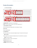
• Connect up to 16 

CAMERA INPUTS 

as necessary.   

• Connect one or more monitors to the DVR using the 

COMPOSITE

,

 VGA 

connections. 

• Connect power to the DVR, using the provided AC power cord or DC 12V Power Adapter (depending on model). 

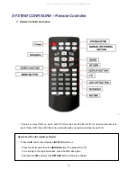
      The DVR will check for proper power connection and emits two beeps if system power test is OK. 

• Press the 

POWER BUTTON 

on the front panel of the DVR to begin operation. 


- The DVR startup screen detects and checks the status 

of hard drive. 


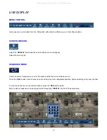
- After startup diagnostics are complete, the operator must 

login to the system. The default user name is ‘

ADMIN

’. 

- Using the 

CHANNEL SELECTION 

buttons, key in the digits of 

the default password (‘

1234

’) and then press the 

ENTER 

button. 


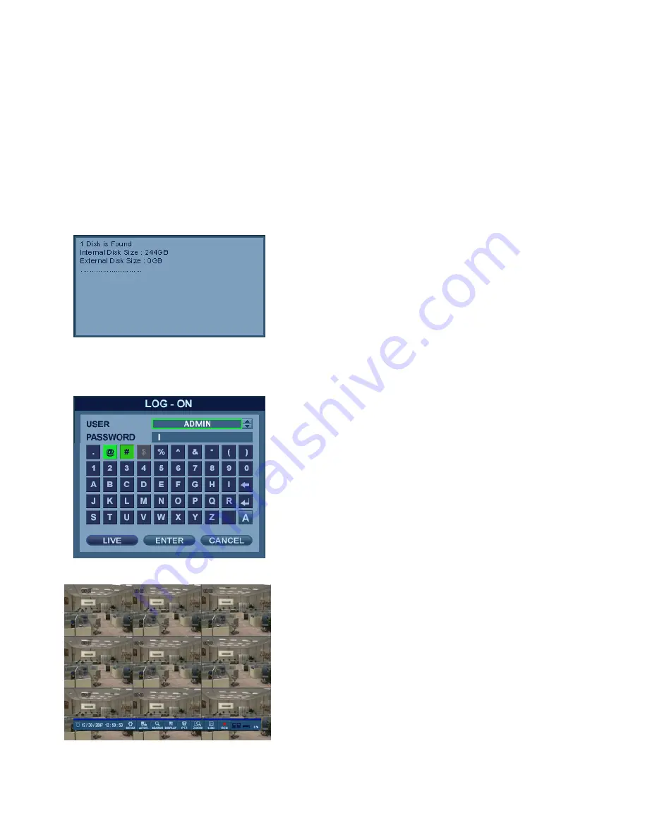
- After DVR startup, the system will show the default display of   

all 16 channels in a standard 4x4 Screen Division mode. 

- The status bar at the bottom of the screen shows the current   

Date/Time and the percentage of Hard Drive capacity used. 

- The title for each channel is shown. 

- A red recording icon and the letter ‘C’ in the top right of each 

channel display shows that the channel is recording in   

Continuous / Schedule mode. 


All manuals and user guides at all-guides.com

Summary of Contents for GANZ Digimaster Series

Page 1: ...1 All manuals and user guides at all guides com a l l g u i d e s c o m ...

Page 2: ... 1 8 C o n n e c t P o w e r O n 1 9 L i v e D i s p l a y 2 0 M e n u C o n t r o l 2 0 S c r e e n D i v i s i o n 2 0 S e q u e n c e 2 0 P T Z 2 1 D i g i t a l Z o o m 2 1 L o g S e a r c h 2 2 P a n i c R e c o r d i n g 2 2 Q u i c k M e n u 2 3 S Y S T E M S E T U P 2 4 C a m e r a 2 5 C a m e r a S e t u p 2 5 C o l o r S e t u p 2 5 P T Z S e t u p 2 6 M o t i o n S e n s o r 2 8 D i s p...

Page 3: ...e r a t i o n s 4 7 C o n t i n u o u s M o t i o n R e c o r d i n g S e t u p 4 8 A l a r m R e c o r d i n g S e t u p 5 2 P a n i c R e c o r d i n g S e t u p 5 2 N e t w o r k S t r e a m i n g S e t u p 5 3 S E A R C H 5 4 S e a r c h B y T i m e 5 4 S e a r c h B y E v e n t 5 7 A R C H I V I N G 5 9 C r e a t e a N e w A r c h i v e 5 9 R e s e r v e d D a t a M a n a g e m e n t 6 0 W E ...

Page 4: ... S y s t e m 6 9 R e c o r d i n g 6 9 U s e r 7 0 N e t w o r k 7 0 S e n s o r 7 1 I n f o r m a t i o n 7 1 WAT E R M A R K P R O C E S S 7 2 S M A R T P H O N E C O N N E C T I O N 7 4 All manuals and user guides at all guides com ...

Page 5: ...16HL This manual describes the external features of GANZ DIGIMASTER part names correct connection methods for supported domes or pan tilt receivers control devices peripheral devices and the system setup instructions It is important to note here that some features figures pictures and references can only be applied to just one model GANZ cannot be held responsible if the DVR is damaged due to the ...

Page 6: ...re of the following precautions before installing the DVR Avoid positioning the DVR in any place where the unit may come into contact with moisture dust or soot Avoid placing in direct sunlight or near heating appliances Keep the product away from electric shock or magnetic substances Avoid temperature extremes recommended operation temperature is between 0 C and 40 C Do not place any conductive m...

Page 7: ...7 The following are warnings and precautions to ensure user safety and prevention of property damage Please read the information below thoroughly All manuals and user guides at all guides com ...

Page 8: ...8 All manuals and user guides at all guides com ...

Page 9: ...9 All manuals and user guides at all guides com ...

Page 10: ...10 All manuals and user guides at all guides com ...

Page 11: ...nly use attachments or accessories that are specified by the manufacturer 12 Use only with a cart stand tripod bracket or table specified by the manufacturer or sold with the apparatus When a cart is used use caution when moving the cart apparatus combination to avoid injury from tip over 13 Unplug this apparatus if outlet is unprotected during a lightning storm or when unused for long periods of ...

Page 12: ...ction 22x15 grid Sensitivity Levels 10 1 lowest 10 highest Multitasking Triplex Video Inputs 8 16 x 1Vp p CVBS 75 ohms BNC Monitor Outputs 1 x CVBS VGA Spot Output 1 x 1Vp p CVBS 75 ohms BNC Audio Inputs 4 x line in mono line level unbalanced RCA jack Audio Output 1 x line out mono line level unbalanced RCA jack Resolution 352x240 704x240 704x480 NTSC 352x288 704x288 704x576 PAL Compression Standa...

Page 13: ...earch Playback Configuration Archiving Support for CMS Software Web R A and Smart Phone Digital Watermark Watermarked Video Audio for verification of data integrity continuity PTZ Control RS 485 Serial interface full duplex two wires Supply Voltage 12VDC 5A 100VAC 240VAC 60 50Hz Operating Temperature Range 5 to 40 Housing Materials Case Cover Steel metal Front Panel Molded Plastic Dimensions HxWxD...

Page 14: ...l of the product contents are present after opening the product packaging Remote Controller Instruction Manual Installation CD AC Power Cable Optional Contents Internal Hard Disk Drive DR8 16HL Unit 12V DC Adapter AAA Battery x 2 Basic Contents All manuals and user guides at all guides com ...

Page 15: ...15 Specifications Organization 3 System Organization VGA Monitor All manuals and user guides at all guides com ...

Page 16: ...lay and playback SEARCH Displays the search menu MENU Displays the setup menus NAVIGATION KEYS Use for navigating on menu or control PTZ RETURN Cancel or go to previous menu Increases reverse playback speed Increases forward playback speed ΙΙ Pauses resumes playback All manuals and user guides at all guides com a l l g u i d e s c o m ...

Page 17: ...ge Camera input type E ALARM INPUTS Up to 4 alarm inputs can be connected and configured as high or low inputs with common ground RELAY OUTPUT 1 alarm outputs can be connected and configured as high or low outputs with common ground RS485 Connect PTZ camera F LAN LAN connection to a router or internal network G MONITOR Main BNC monitor SPOT OUT BNC Spot monitor H POWER Connect 12V 3 33A adaptor A ...

Page 18: ...ets each ID per DVR then all DVRs can be controlled with one remote controller by each ID How to set ID on the remote controller Press the ID button then displayed INPUT ID statement Press the set ID and Press the RETURN button The default ID is 01 For returning to the original situation press the ID button again And Input the 255 and press the RETURN button of remote controller All manuals and us...

Page 19: ...hard drive After startup diagnostics are complete the operator must login to the system The default user name is ADMIN Using the CHANNEL SELECTION buttons key in the digits of the default password 1234 and then press the ENTER button After DVR startup the system will show the default display of all 16 channels in a standard 4x4 Screen Division mode The status bar at the bottom of the screen shows ...

Page 20: ...ct the screen type SEQUENCE MODE User can select a sequence as one of the options within the screen division menu Press the SEQ button Each channel is shown full screen for an adjustable duration before switching to the next channel To stop the sequence on a particular channel press the SEQ button again More complex sequences can be programmed through the DISPLAY section of the setup menu All manu...

Page 21: ...button and another window will appear User can select an item from the PTZ parameter menu and edit the settings in order to fine tune the speed of pan tilt zoom motions or to enable advanced features such as Auto Focus and Auto Iris only on supported PTZ devices DIGITAL ZOOM Right Click within Live View mode and choose ZOOM Or select the ZOOM function from the status bar While viewing a channel in...

Page 22: ...e the Panic Recording mode On Off When Panic Recording mode is enabled you will see a red recording icon with P for Panic When Panic Recording mode is enabled the system will record all channels as per the Panic Recording settings All resolution and image rate settings related to Panic Recording are configured within the Record menu All manuals and user guides at all guides com ...

Page 23: ...the live display of any channel While the other channels will continue to show live view video the frozen channel display is stopped Click once more to return to live view video 2 PTZ Please refer to PTZ menu of Page 21 3 Zoom Please refer to ZOOM menu of Page 21 4 PANIC REC Start Stop Please refer to Panic Record menu of Page 22 All manuals and user guides at all guides com ...

Page 24: ...RETURN buttons In general the ENTER button is used to select a particular field to edit and then is pressed again to confirm changes The RETURN button is used to cancel or deselect or to step back one screen while navigating the menu system To configure all system settings highlight SYSTEM SETUP and press ENTER All manuals and user guides at all guides com ...

Page 25: ...e is not displayed in live display but continues to be recorded AUDIO Determines the audio recording channel which will be paired with each video channel CAMERA COLOR SETUP While modifying any value within the color setup the selected channel will be displayed full screen BRIGHTNESS CONTRAST TINT and COLOR can be modified as necessary To modify a different channel highlight the CAMERA field and ch...

Page 26: ...oose the desired channel Press RETURN when all changes are completed CAMERA PTZ SETUP Click the PTZ SETUP menu Click on any field to modify its value Change the value by the button ADDRESS The unique ID of the PTZ device PROTOCOL The protocol of the PTZ device BAUD RATE The baud rate of the PTZ device DETAIL Detail setting for PTZ device Refer to the next page All manuals and user guides at all gu...

Page 27: ... adjusted for each channel using the DETAIL button Some settings such as Auto Focus may not be compatible with all PTZ devices If this is the case changing this value will have no effect on PTZ control All manuals and user guides at all guides com ...

Page 28: ...o edit the motion detection area AREA SETUP Choose this option to define which areas of the image are sensitive to motion Click on individual squares to select or deselect each square Click and drag to select or deselect entire areas of the grid To quickly select or deselect the entire grid at once right click and choose either SELECT ALL or DESELECT ALL Red outlined grid area Selected area White ...

Page 29: ...id is set to ON the user can choose the color of the grid MOTION SENSOR DISPLAY This feature can be used to determine which areas within a channel are detecting motion in real time The motion sensor display can be used to troubleshoot false motion activations OFF normal display mode ON areas where motion is detected are highlighted with colored blocks MOTION COLOR The color of the blocks displayed...

Page 30: ...s displayed after an alarm input If the alarm condition continues the pop up screen will be displayed constantly MOTION POP UP MODE When enabled motion detection will cause the associated channel to display full screen MOTION POP UP DWELL Determines how long the full screen popup is displayed after motion detection If motion continues the popup screen is displayed constantly To change any of these...

Page 31: ...en views which can be comprised of any number of channels in any order To add a new sequence highlight ADD and press ENTER Click the ADD button to add a new sequence Sequence Title is highlighted Press ENTER to bring up the virtual keyboard and key in a name for the new sequence Click on the ACTIVATION field and click the button to turn the sequence activation ON Select SAVE Then the menu pictured...

Page 32: ... sequence settings have been entered correctly click CONFIRM To add an additional mode click ADD continuously After finishing the setup click CLOSE To modify the current pattern double click it The Sequence Setup window will appear again The new sequence has now been saved and can be started by pressing the SEQ button while in Live View mode All manuals and user guides at all guides com ...

Page 33: ...ce By default Spot Monitor output is set to run a sequence of all 16 channels SPOT TITLE Input the title of each spot monitor ACTIVATION Toggle each spot monitor ON OFF Click MODIFY Below is default setup To modify the current display double click the display Then Spot Sequence Setup window will appear Setup method is similar to the Sequence setup performed earlier can only use single or quad mode...

Page 34: ... Specify which one of the 4 AUDIO INPUTS is routed to the AUDIO OUTPUT NETWORK AUDIO TX When enabled live and playback audio is transmitted to a remote PC connection NETWORK AUDIO RX When enabled allows a remote PC connection to send audio back to the DVR SOUND BUZZER Click on the BUZZER menu and click on any field Use the button to modify each value KEYPAD When enabled each front panel button key...

Page 35: ...n which the date is displayed MM DD YYYY TIME FORMAT Determines how the time is displayed AM PM or 24 hour NETWORK TIME SERVER SETUP If the DVR is connected to the Internet the time and date can be accurately set by selecting SYNC and pressing ENTER TIME ZONE SETUP should be set according to the region that the DVR is used in D S T When enabled the DVR will automatically adjust for daylight saving...

Page 36: ...the manual IP address entered in the NETWORK menu or the automatic IP address assigned by a DHCP server if enabled MAC ADDRESS Shows the MAC Media Access Control address of the DVR It is a unique identifier no other network device has the same MAC address DDNS DOMAIN NAME If DDNS is enabled the host DDNS server is specified here RTSP SERVICE PORT The port number that the DVR uses to support remote...

Page 37: ...ed to another DVR if multiple units need to be installed with the same settings All information is saved apart from network settings and system name PASSWORD Determines whether the system must be used every time when entering the menu system PASSWORD EXPIRED Determines the amount of time before the system password expires SYSTEM CONTROL DEVICE Click on the CONTROL DEVICE menu This will allow up to...

Page 38: ...ount double click on the user name After changing click OK to confirm changes USER ID Edit the User ID using the virtual keyboard maximum of 10 characters PASSWORD Change the password using the virtual keyboard maximum of 4 characters GROUP Users can be assigned to one of three groups ADMIN MANAGER or USER see User Authority setup E MAIL Enter the user s e mail address if e mail notification is re...

Page 39: ...utton after selecting each of the desired items NOTE Any user can be deleted except the default ADMIN user account USER LOG OUT AUTO LOGOUT Determines whether a logged in user is automatically logged out of the menu DURATION Determines the amount of time before a logged in user is automatically logged out of the menu All manuals and user guides at all guides com ...

Page 40: ...by the user 1ST DNS SERVER If DHCP is not being used the first DNS server can be manually set by the user 2ND DNS SERVER If DHCP is not being used the second DNS server can be manually set by the user RTSP SERVICE PORT If the connected Router supports UPnP Universal Plug and Play functionality when you click AUTO PORT the port forwarding is automatically configured WEB SERVER PORT The port number ...

Page 41: ...DDNS Host Name a 00115ff00213 dvrlink net b 1234 dvrlink neet user can choose any DDNS Host Name NETWORK E MAIL Click on the E MAIL submenu SERVER The SMTP outgoing e mail server that will be used to send e mail notifications PORT The outbound e mail service port number SECURITY Turn OFF if the SERVER does not require a username and password for SMTP authorization USER Enter the user name for the ...

Page 42: ...R T Self Monitoring Analysis and Reporting Technology hard disk monitoring CHECK INTERVAL Frequency of testing DISK FULL EVENT Determines whether a Disk Full condition would result in a HDD event EVENT SENSOR ALARM INPUT Click on the ALARM INPUT menu and choose any field Use the button to modify the value The menu will determine the behavior of each of the 4 alarm inputs OPERATION Alarm inputs can...

Page 43: ...igger DURATION In LATCHED mode the amount of time that the alarm output remains active after it has been triggered TYPE Can be set to high 0V to 5V when activated or low 5V to 0V when activated HDD EVENT Determines whether a hard drive event will trigger an alarm output Action settings ALARM Determines whether the specific channel alarm input would trigger the alarm output VIDEO LOSS Determines wh...

Page 44: ...he trigger criteria is present or LATCHED the buzzer sounds for a set period of time after the trigger DURATION In LATCHED mode the time that the buzzer will continue to sound after it has been triggered Action settings ALARM Determines whether alarm inputs will activate the internal buzzer VIDEO LOSS Determines whether video loss on any of the selected channels will sound the internal buzzer MOTI...

Page 45: ... hard drive event would cause an e mail to be sent BOOTING EVENT Determines whether a booting event would cause an e mail to be sent Action settings ALARM Determine whether alarm inputs will cause an e mail to be sent VIDEO LOSS Determine whether video loss on any of the selected channels will cause an e mail to be sent MOTION Determine whether motion detection on any of the selected channels will...

Page 46: ...l start overwriting the earliest recorded footage once the hard drive is full In this case the percentage of hard drive used shown in live display will always be 99 When disabled the DVR will stop recording when the disk becomes full FORMAT If necessary all recorded footage can be erased from the DVR using this option NOTE When the RECORD TIME LIMIT is set the percentage of HDD used shown in live ...

Page 47: ...every day of the week or WEEKLY each day of the week has its own schedule PRE EVENT RECORDING TIME When the DVR is not in continuous recording mode this setting determines the amount of footage that is always recorded before an event occurs motion detection alarm input etc POST EVENT RECORDING TIME When the DVR is not in continuous recording mode this setting determines the amount of footage that ...

Page 48: ...09 00 and 18 00 or by each individual hour Note that when SCHEDULE MODE is set to WEEKLY each day of the week can be individually configured ACTIVATION This section determines at what times the DVR will record and whether it is set to continuous or motion SIZE FPS QUALITY Click on the SIZE FPS QUALITY tab To change SIZE FPS QUALITY settings highlight CONTINUOUS MOTION SETUP and press ENTER Ensure ...

Page 49: ...me bar shows the recording settings for this time period Click and drag on the TIMELINE to select a block of time Example To change the recording settings between 09 00 and 18 00 Use the CURSOR KEYS to move the green cursor to the 09 00 position and press ENTER The cursor changes to orange to show the start position Use the CURSOR KEYS to stretch the orange cursor across to the 18 00 position All ...

Page 50: ...l will play back at the same time Adjust the values as desired and select OK to finish and return to the parameter menu Other time periods can be configured in the same manner NOTE Remember that if the SCHEDULE MODE is set to WEEKLY recording settings need to be changed for each day as well as for each particular time NOTE DR16HL supports a maximum recording rate across all channels of 480 400 ima...

Page 51: ...g only between 18 00 and 00 00 Use the CURSOR KEYS to move the green cursor to the 18 00 position and press ENTER The cursor changes to orange to show the start position The schedule grid uses differently colored blocks to denote the different recording modes NO COLOR blocks No recording LIGHT BLUE blocks The DVR will record continuously DARK BLUE blocks The DVR will only record while motion is de...

Page 52: ...he CONTINUOUS MOTION RECORDING menu for details on setting up the SIZE FPS QUALITY and ACTIVATION tabs within the ALARM RECORDING menu Alarm activated recording can be used in conjunction with the CONTINUOUS MOTION RECORDING menu The DVR can be configured to record continuously at a low image rate CONTINUOUS MOTION RECORDING menu and then increase to a higher image rate during an alarm condition A...

Page 53: ...elect the Size FPS Quality and audio During Network Streaming mode the DVR is possible to set remotely uploaded video audio stream with using client program like Web RA Maximum recording frame rate is 120FPS at resolution of 1CIF 352x240 All manuals and user guides at all guides com ...

Page 54: ...sired search date from the calendar The DVR uses a calendar and timeline search method for quick access to recorded footage The calendar displayed on the left side of the screen shows the current month Days which have any recorded footage will be highlighted in green The timeline on the right side of the screen shows a 24 hour status of all channels for the selected day Each block represents 15 mi...

Page 55: ...otage for that day Press ENTER to choose the date and move to the timeline Click the PLAY button on the bottom of the screen Use the CURSOR KEYS to move the timeline cursor left or right to select the desired time segment Each movement of the timeline cursor increases or decreases the time by 15 minutes The currently selected time is displayed above the calendar Press ENTER to begin playback from ...

Page 56: ...ain RESERVE Press this button to reserve the currently selected data CONTINUE Press this button to go back and reserve more data The system will return to playback mode START Press this button to start the reservation STOP Make sure to press this button to reserve the current data first Then user can select RESERVE CLOSE Close the reservation menu and finish archiving NOTE Reserved data will be ke...

Page 57: ...CH BY EVENT The DVR event log stores events such as motion and alarm activated recording video loss etc To search for an event and playback the recorded footage press the SEARCH button and log in as ADMIN with the default password of 1234 Click the SEARCH BY EVENT menu Check all desired options Use the buttons to select the desired date and time range to search for events All manuals and user guid...

Page 58: ...ns can be used as normal To stop playback and return to live view mode repeatedly press the RETURN button The event log search contains the following selectable entries ALARM When this option is checked all alarm input events are displayed for the chosen date range TIMER When this option is checked scheduled recording operations are displayed for the chosen date range MOTION When this option is ch...

Page 59: ...ngs Use the button to modify each value Click QUERY to view the data size of the selected clip It is useful to use QUERY first before selecting BURN or RESERVE Press the RELEASE button to reset the results from any previous QUERY RESERVE Press this after inputting the TAG name to reserve the selected clip BURN Press this after inputting the TAG name Then press START after viewing the confirmation ...

Page 60: ...mount of available space on the backup media the END TIME of the archive is adjusted accordingly The MODIFIED SIZE is the final file size of the archive Select OK and press ENTER to begin the archiving process Once extracted the footage is copied to USB Depending on the amount of footage selected for archive the extracting and burning process may take some time during which the operating system of...

Page 61: ...AM 512MB or higher Video Card GeForce MS 400 ATI Radeon 7500 or higher GeForce 8 Series or higher Video RAM 64MB or higher Monitor 1280x1024 Operating System Windows XP Service Pack 2 or higher Web Browser IE 6 0 or higher Network LAN at least 100Mbps DirectX Version 7 0 or higher HOW TO CONNECT Input the IP address or URL of the DVR into the Address Bar of your web browser If using a DDNS service...

Page 62: ...will need to install the ActiveX control click Run Add on In case of not being able to install ActiveX the user needs to enable ActiveX within the IE security menu Select Enable for all ActiveX related options Download signed ActiveX controls Download unsigned ActiveX controls etc All manuals and user guides at all guides com ...

Page 63: ...ion 1 4 8 9 16 channel modes Sequence Mode Move to Next Camera Full Screen Select Live View Channel Manually Activate Microphone to send audio to the DVR audio out jack Toggle Network Audio Receive from DVR Save the current live image Print the current live image Take a Snapshot of the current live image All manuals and user guides at all guides com ...

Page 64: ...tion 3 Video Loss indicator will be marked when system detects Video Loss 4 Recording Display current recording mode T Timer or Continuous M Motion A Alarm Recording 5 Alarm Out indicator will be marked when system detects Alarm Output 6 Refresh Time interval for the information on the status panel to refresh Log Display the system event log in real time PTZ Control any connected PTZ camera remote...

Page 65: ... two or more preset points SEARCH BY TIME Select a position on the timeline or set an exact time Press the Play button to begin playback from the selected position 1 Refresh Refresh all data indicators on the recording table 2 Play Initiate playback of recorded data from the current position on the timeline 3 Backup User can archive recorded data remotely from the DVR to the local PC All manuals a...

Page 66: ...d data 2 Period Set the date time range to search for events within the recorded data 3 Search Begin query and list all events found within selected range and type 4 Double click an event from the list to initiate playback with the specific channel shown in full screen mode All manuals and user guides at all guides com a l l g u i d e s c o m ...

Page 67: ... S SE ET TU UP P REMOTE SETUP 1 CAMERA User can configure all camera attributes such as title covert channel PTZ or motion Motion Area Setup for individually configuring motion areas and sensitivity All manuals and user guides at all guides com ...

Page 68: ...nnel and the motion sensitivity level 3 Click and drag the mouse across the image grid to select motion areas 4 Click OK 2 DISPLAY 1 OSD Configure properties for the on screen display OSD of the DVR 2 Monitor Set dwell time for sequence spot monitor output and pop up functions All manuals and user guides at all guides com ...

Page 69: ...etting Activate DVR internal buzzer based on keypress 4 System Configure Date and Time Formats NTP Time Server Time Zone and DST properties 5 Recording User can configure all of the recording parameters and schedules This is similar to the procedure for configuring these properties on the DVR system All manuals and user guides at all guides com ...

Page 70: ...time 7 Network User can check the DVR network information and adjust the network bandwidth throttle All other IP settings are not allowed to be changed remotely These settings can only be changed locally For setting up e mail notification user can configure the SMTP server details remotely All manuals and user guides at all guides com ...

Page 71: ...ions for Alarm Input Alarm Output Buzzer Out and E Mail Notification The menu structure is very similar to the local DVR system setup for Event Sensor INFORMATION Displays the DVR Model and WEB Remote Software Version All manuals and user guides at all guides com a l l g u i d e s c o m ...

Page 72: ... OC CE ES SS S 1 Open the archive data and Run the file bplayer exe which is included within the backup folder 2 Click the Open File button and choose the backup file you wish to open and verify All manuals and user guides at all guides com ...

Page 73: ... file you will be asked to confirm whether or not you would like to check the watermark 4 Click the Yes button to verify the embedded watermark 5 If the archived AVI file has been modified a Verification Failed message will appear All manuals and user guides at all guides com ...

Page 74: ... NE E C CO ON NN NE EC CT TI IO ON N iPhone 1 Select the Safari browser 2 Enter the IP address or URL to connect Click the GO button 3 Enter the User ID and Password Default ADMIN 1234 All manuals and user guides at all guides com ...

Page 75: ...E C CO ON NN NE EC CT TI IO ON N BlackBerry 1 Select the Web browser 2 Enter the IP address or URL to connect and press the Enter button 3 Enter the User ID and Password Default ADMIN 1234 All manuals and user guides at all guides com ...

Page 76: ...76 All manuals and user guides at all guides com a l l g u i d e s c o m ...

Page 77: ...77 All manuals and user guides at all guides com ...

Page 78: ...78 All manuals and user guides at all guides com ...

Reviews: