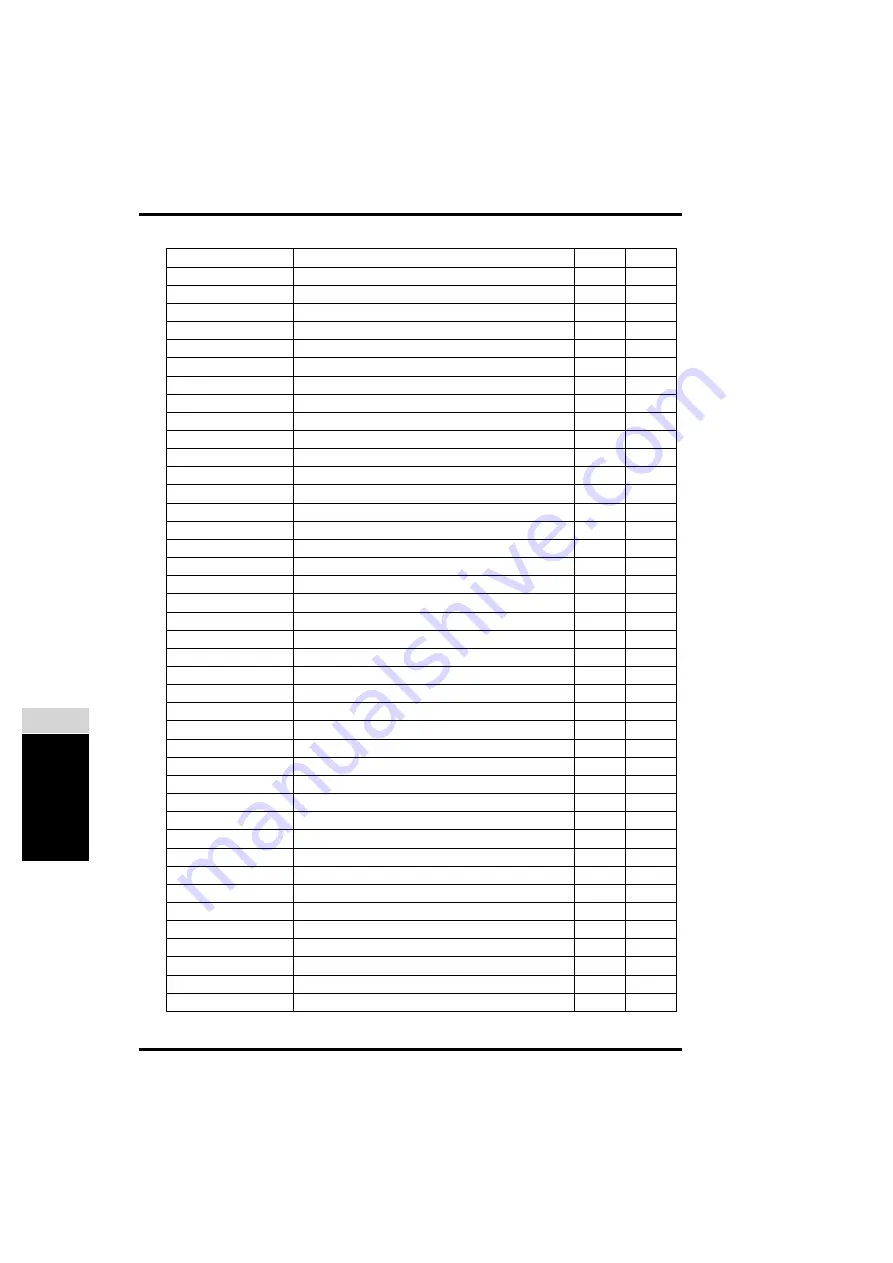
Cawomat 2000 IR Reference Manual Download Page 130

P

a

rt

s Li

st

B

126

1220C GB 19991004

CM+9.9460.2105.0

BEARING

121

10

CM+9.9460.2106.0

BEARING

121

11

CM+9.9460.2258.0

BEARING

99

07

CM+9.9460.2330.1

ROLLER

101

04

CM+9.9460.2330.1

ROLLER

115

06

CM+9.9460.2561.0

COVER

97

13

CM+9.9460.2562.1

SETTING KNOB

97

14

CM+9.9460.2590.0

STEP SWITCH

97

15

CM+9.9462.1017.3

TABLE PLATE

93

13

CM+9.9462.1019.1

MEASURING PIN

93

14

CM+9.9462.1021.0

MOUNTING PLATE

117

01

CM+9.9462.1027.0

SPUR GEAR

103

30

CM+9.9462.1027.0

SPUR GEAR

109

30

CM+9.9462.1027.0

SPUR GEAR

111

29

CM+9.9462.1034.2

SNAP SPRING

93

15

CM+9.9462.1035.0

REDUCING PART

93

16

CM+9.9462.1043.0

RED BOTTLE RECEPTACLE (DEVELOPER)

93

18

CM+9.9462.1044.0

BLUE BOTTLE RECEPTACLE (FIXER)

93

19

CM+9.9462.1045.0

WHITE BOTTLE RECEPTACLE (WATER)

93

20

CM+9.9462.1052.2

PIN

93

21

CM+9.9462.1105.0

PROTECTING CAP

93

23

CM+9.9462.1106.0

HOLDER

93

24

CM+9.9462.1107.0

HOLDER

93

25

CM+9.9462.1111.1

SNAP CASE

93

26

CM+9.9462.1175.0

COVER

93

40

CM+9.9462.1202.3

SHAFT

97

08

CM+9.9462.1203.2

SHAFT

99

09

CM+9.9462.1204.0

HELICAL SPUR GEAR

99

10

CM+9.9462.1205.1

SHAFT

99

11

CM+9.9462.1206.0

HELICAL SPUR GEAR

99

12

CM+9.9462.1207.1

SHAFT

97

18

CM+9.9462.1211.1

SHAFT 

99

13

CM+9.9462.1212.0

HELICAL SPUR GEAR

99

14

CM+9.9462.1213.2

SHAFT

99

15

CM+9.9462.1214.0

HELICAL SPUR GEAR

99

16

CM+9.9462.1215.0

PIPE UNION

99

17

CM+9.9462.1218.0

SPUR GEAR

99

18

CM+9.9462.1219.1

TRANSFER GEAR

97

09

CM+9.9462.1221.1

PLATE

99

19

CM+9.9462.1252.3

BUSHING

97

24

CM+9.9462.1253.3

BUSHING

99

21

Part code

Description

Page

Item

Summary of Contents for 2000 IR

Page 1: ...CAWOMAT 2000 IR Reference manual Cawomat 2000 IR 1220C Cawomat 2000 IR RM 07 10 99 14 17 Page p1...

Page 2: ...is document and specif ically disclaims warranties of suitability for any particular purpose CAWO Photochemische Fabrik GmbH shall under no circumstances be liable for any damage arising from the use...

Page 3: ...eparing the chemicals 25 Checking the replenishment rates 27 Replenishment rate adjustment 29 Using the Cawomat 2000 IR 31 Chapter 3 Cleaning the Cawomat 2000 IR 33 Cleaning frequency 35 General clean...

Page 4: ...ce of the main drive assembly 64 Adjustment of replenishment pump gears 79 Replacement of roller springs 81 Appendix A Equipment information sheet 83 Specifications 85 Safety standards 88 Appendix B P...

Page 5: ...Preface Introducing the Cawomat 2000 IR 1220C Cawomat 2000 IR RM 07 10 99 14 17 Page 1...

Page 6: ...1220C GB 19991004 2 Preface 0 1220C Cawomat 2000 IR RM 07 10 99 14 17 Page 2...

Page 7: ...350 mm 14 wide and 1200 mm 51 long Easy to handle compact in size light in weight No installation cost Just plug it in No extra plumbing no fixed water supply or water drainage system required Low op...

Page 8: ...ing Chapter 4 Troubleshooting serves as a guide to recognize identify and solve possible errors and problems Chapter 5 Advanced service instructions for skilled personnel describes maintenance and rep...

Page 9: ...the processor must be operated cared for and ser viced correctly as described in the documentation provided with the machine If the processor is not operated correctly or if you do not have it servic...

Page 10: ...with cold water and consult a physician Do not inhale vapor from chemicals Make sure that there is sufficient ventilation where the processor is installed i e air exchange that is at least ten times...

Page 11: ...by step description of the installation and unpacking procedure for the Cawomat 2000 IR Basic installation requirements Installation 1 Chapter Installation of the Cawomat 2000 IR 1220C Cawomat 2000 I...

Page 12: ...1220C GB 19991004 8 Installation 1 1220C Cawomat 2000 IR RM 07 10 99 14 17 Page 8...

Page 13: ...ormal room temperature 15 C to 25 C 59 F to 77 F A convenient sink and water hose is recommended for filling the water replenishing bottle for mixing the chemicals and for cleaning the processor An op...

Page 14: ...rom all sides if possi ble but a minimum clearance must be provided Consult the diagram The Cawomat 2000 IR Support Table is an option meeting exactly all re quirements it features appropriate support...

Page 15: ...as a pivot point The drain hoses are held in place by rubber bands 2 Withdraw and unroll the three drain hoses If the processor has been placed as shown above you see from the left to the right the d...

Page 16: ...e water hose can be put together into one bottle However the fixer hose should be put into a second waste bottle 5 Correct the hose length If the processor is to be installed on a counter with the was...

Page 17: ...front to back and left to right preferably on the tank rollers as shown in the figures above Turn the levelling screws clockwise to raise the processor and counter clockwise to lower the processor Tu...

Page 18: ...om its polyfoam wrapping 2 Engage the left hook of the exit tray in the slot on the left of the dryer cover 3 Engage the right hook of the exit tray in the leftmost ventilation slot on the right side...

Page 19: ...shment bottles have the correct valves attached The valves are color coded to match them to their corresponding bottles to avoid conta mination of the chemicals Refer to the table on page 36 for the a...

Page 20: ...dark room safely once processing of films has started Refer to Appendix A for order codes and specifications 1 Remove the light tight cover accessory from its packing 2 Slide the light tight cover on...

Page 21: ...d to the water source 1 805 cm 3 4 pipe with shut off valve The connection is a male union with a 0 953 3 8 O D thread Set the pressure reducing valve to the values as indicated in the diagram 3 Remov...

Page 22: ...1220C GB 19991004 18 Installation 1 1220C Cawomat 2000 IR RM 07 10 99 14 18 Page 18...

Page 23: ...ains some key concepts Main components Control panel Preparing the chemicals Checking the replenishment rates Replenishment rate adjustment Using the Cawomat 2000 IR 2 Chapter Getting Started with the...

Page 24: ...1220C GB 19991004 20 Getting started 2 1220C Cawomat 2000 IR RM 07 10 99 14 18 Page 20...

Page 25: ...oper heater 7 Fixer tank guide plate 20 Developer thermal cutout 8 Water replenishment bottle 21 Fixer heater 9 Wash water tank guide plate 22 Fixer thermal cutout 10 Control panel 23 Heater cables 11...

Page 26: ...replenishment and dryer systems and then passes through the developer the fixer and the wash water tanks After drying the film leaves the dryer section and is deposited into the exit tray 1 Feed sect...

Page 27: ...tion causes the contents of the developer tank fix er tank and wash water tank to rise in their pump tubes and flow into the drains An appropriate amount of fresh solution and wash water is replenishe...

Page 28: ...ual replenishment key allows the user to initiate an addi tional replenishment cycle during which a red indicator light is il luminated The manual replenishment key should be pressed if the processor...

Page 29: ...visable to wear rubber gloves and to wash your hands thoroughly af terwards Always prepare the solutions in accordance with the directions from your supplier Read the accompanying leaflet and or the i...

Page 30: ...cal each for making up 2 5 litres of fixer solution if you want to make up 5 litres of working solution double the values for water and chemicals in the procedure below 1 Fill up the blue marked reple...

Page 31: ...umstances After installation of the machine After replacement of the pumps If the standard film size is altered The replenishment pumps have been factory set for average replenishment rates based on p...

Page 32: ...f liquids 15 tolerance flowing into the tanks during a replenishment period of approximately 3 minutes Film sizes Developer Fixer Rinsing water average mix 8 mm 5 16 11 mm 7 16 13 mm 1 2 larger than 2...

Page 33: ...m mended that you wear protective gloves glasses and an apron for your safety 1 Remove the replenishment bottles and the processor cover 2 Carefully free the tank heater cables from their retaining cl...

Page 34: ...rewdriver to prevent it from turning 7 Slide the tank back into position making sure that the drive gears are properly engaged 8 Replace the processor cover and the replenishment bottles 9 Depress the...

Page 35: ...chieve the appropriate operating temperature Additional replenishment If the processor has been idle for more than 24 hours press the manual replen ishment key to initiate an additional replenishment...

Page 36: ...N again This can often solve the problem Switching off After work or at the end of the day switch off the Cawomat 2000 IR as follows 1 Switch off the processor and disconnect the power cord from the o...

Page 37: ...no special skills tools nor training Cleaning frequency General cleaning directions Removal of the tanks Cleaning the tanks Cleaning the processor chassis Cleaning the dryer Reinstalling all parts Cl...

Page 38: ...1220C GB 19991004 34 Cleaning 3 1220C Cawomat 2000 IR RM 07 10 99 14 18 Page 34...

Page 39: ...ttle daily to prevent the forming of algae Follow the switching off procedure as described in the paragraph Using the Cawomat 2000 IR which can be found in chapter 2 Getting started with the Cawomat 2...

Page 40: ...tle valves bottle receptacles tank covers pumps and tanks are color coded to prevent contamination of the chemicals and for ease of assembly after cleaning They must be returned to their proper locati...

Page 41: ...1 Remove the replenishment bottles and processor cover 2 Carefully free the tank heater cables from their retaining clips 3 Slightly lift the tank to be cleaned and pull it forward enough to give fre...

Page 42: ...the tank by releasing the drain valve clamp It may be necessary to gently pull the end of the drain tube to facilitate proper draining Allow liquids to run out For easy flow the drain tube should not...

Page 43: ...de plate to a sink for cleaning 2 Remove the transport rollers from the tank Wash the rollers with a sponge and running water 3 Unfasten the replenishment pump by loosening the two wing nuts and then...

Page 44: ...es on the pumps and the tanks in order to avoid contamination Consult the table on page 36 6 With the drain valve open wash the tank under running water allowing water to drain through the valve After...

Page 45: ...anner to a sink for cleaning 4 Clean the heaters Never hold the plastic part of the heaters in running water or immerse it in a liquid 5 Clean the drainage troughs using a sponge and lukewarm water 6...

Page 46: ...sengage the interlock pin 1 and then slide the cover forward to remove it from its rear holding lip 2 2 Remove and clean the squeegee roller assembly Do not dismantle the squeegee roller assembly Clea...

Page 47: ...e fan compartment with a damp cloth Make sure no water gets into the dryer 5 Reinstall the transport roller assembly Make sure that the dryer transport drive gear is properly engaged 6 Replace the dry...

Page 48: ...rive gears Make sure that the drain valves are fastened in the upright closed position Make sure that the heaters are engaged in their retaining slots Make sure that the heater cables are put back in...

Page 49: ...blems you may encounter while working with the Cawomat 2000 IR Troubleshooting checklist Processor fails to operate Appearance of processed films Film transport problems 4 Chapter Troubleshooting 1220...

Page 50: ...1220C GB 19991004 46 Troubleshooting 4 1220C Cawomat 2000 IR RM 07 10 99 14 18 Page 46...

Page 51: ...ating replenishment or cleaning procedures If you have followed all installation operating and cleaning instructions as described in chapters 1 2 and 3 the problem can be caused by an electrical or me...

Page 52: ...he interlock pins in the dryer and processor covers are engaging the interlock switch The processor cannot work if the interlock switch is not engaged as shown on the figure above 4 If none of the abo...

Page 53: ...ed remove and clean the guide plates with a sponge and lukewarm water Roller marks crosswise 1 Check the condition of the tank transport rollers and the dryer squeegee rollers Remove the processor cov...

Page 54: ...efer to chapter 5 Advanced service instructions for skilled ser vice personnel 5 Check that the developer is not exhausted Drain and clean the developer tank and the replenishment bottle by following...

Page 55: ...h lukewarm water Do not dis mantle the squeegee roller assembly 2 Check the squeegee rollers for stretched retaining springs The retaining springs hold the rollers tightly together Inspect the springs...

Page 56: ...the range of 33 C and 35 C 92 F and 94 F call your local service organization 3 The developer can be improperly mixed or exhausted Drain and clean the developer tank and the replenishment bottle by f...

Page 57: ...velling can result in excessive drainage If you want to level the processor re fer to chapter 1 Installation of the Cawomat 2000 IR Caution Do not put films on or near the dryer Films can get fogged w...

Page 58: ...e dryer Alternatively the problem can be caused by one of the components that drive the gears the gears in the main drive system the drive motor itself or the drive belt Refer to chapter 5 Advanced se...

Page 59: ...nents may become exposed Important safety notice Resetting the thermal cutouts Film drying problems Maintenance of the main drive assembly Adjustment of replenishment pump gears Replacement of roller...

Page 60: ...1220C GB 19991004 56 Advanced service 5 INSTRUCTIONS FOR SKILLED SERVICE PERSONNEL ONLY 1220C Cawomat 2000 IR RM 07 10 99 14 19 Page 56...

Page 61: ...2000 IR during which live electrical or hot components may be come exposed The procedures described hereafter can imply hazardous situations and are therefore to be carried out by skilled service per...

Page 62: ...re that they are properly filled Replenish the tanks if required Refer to chapter 2 Getting started with the Cawomat 2000 IR 3 With tanks properly filled press the reset switch on the appropriate heat...

Page 63: ...enishment system or by adverse temperature or humidity problems You may have to check one or more of the following Mechanical Electrical 1 Check for excess temperature or humidity Ambient temperature...

Page 64: ...IR drain and clean the fixer tank and the re plenishment bottle Replace the fixer tank mix a new solution in the replenishment bottle and reinsert it in the processor The tank will be filled automati...

Page 65: ...check for proper film drying by running an exposed test film Mechanical Replenishment 1 Listen to the sound of the replenishment pump motor If the motor speed does not increase to two times its normal...

Page 66: ...e pump gears must be properly engaged with their associated drive gear If either or both gears are defective or worn replenishment will be affected The height of the pump gear is critical to gear enga...

Page 67: ...cement instructions refer to Maintenance of the main drive assembly 5 The problem can also be a broken or slipping replenishment pump drive belt This belt simultaneously drives the three pumps For a l...

Page 68: ...and suitable protection should be worn Remove the replen ishment bottles drain the tanks and then rinse the parts in water in order to remove all chemicals The parts can now safely be handled without...

Page 69: ...transfer gear 13 Main worm drive shaft 7 Smaller transfer gear The diagram below gives an overview of the main components of a drive gear shaft However individual drive gears can be assembled differe...

Page 70: ...the processor cover and tank covers 3 Pull the tanks out partially and drain them Refer to chapter 3 Cleaning the Cawomat 2000 IR 4 Remove the two screws securing the rear cover using a screwdriver a...

Page 71: ...After locating a defective gear removal and replacement follow this general pro cedure 1 Remove the snap ring by prying it off 2 Withdraw the gear slowly from its shaft so as not to lose any spacers o...

Page 72: ...place the snap ring If a snap ring has been lost or damaged replace it with a new one 5 Check the assembly by turning the drive gear with your finger If the drive roller turns smoothly all parts can b...

Page 73: ...cers and washers in the same position 4 Replace the snap ring If a snap ring has been lost or damaged replace it with a new one 5 Check the assembly by turning the drive gear with your finger If the d...

Page 74: ...pump 1 Unfasten the replenishment pump by loosening the two wing nuts and then pull the pump out 2 By prying it off remove the snap ring that holds the pump gear onto the pump shaft 70 Advanced servic...

Page 75: ...aft Use the same number of spacers and washers in the same position Refer to Adjustment of replenishment pump gears if the pump is not properly en gaged with its associate drive gear 5 Replace the sna...

Page 76: ...drive gear however can be replaced if it is damaged 1 Remove the snap ring by prying it off 2 Withdraw the damaged gear slowly from its shaft 3 Slide a new red drive gear on the shaft 4 Replace the sn...

Page 77: ...ion The drive gear however can be replaced if it is damaged 1 Remove the snap ring by prying it off 2 Withdraw the damaged gear slowly from its shaft 3 Slide a new drive gear on the shaft 4 Replace th...

Page 78: ...lowing 1 Remove the snap ring and the spacer on the worm drive shaft side of the processor 2 Slide the drive gear off its shaft The cylinder pin is removable so be careful not to drop it 3 Slide the n...

Page 79: ...Be careful not to drop any components 4 On the opposite side pull the shaft out Transport drive gear shafts are pulled out at the chemical tanks side 5 Replace the defective shaft bearing s from the...

Page 80: ...ler transfer gear 2 shaft and remove the plastic retaining disc 2 Disengage the replenishment pump drive belt 1 from the sprockets of the smaller transfer gear 3 Disengage the motor drive belt 2 from...

Page 81: ...retaining disc and the keeper on the transfer gear shaft Replacement of the replenishment pump drive belt The replacement of the replenishment pump drive belt is not user serviceable Call your local...

Page 82: ...covers and the processor cover Make sure that the interlock switch indicated on the processor cover with a white dot is properly engaging the interlock switch If not the processor will fail to operat...

Page 83: ...be reused as they are not sub ject to wear Refer to chapter 3 Cleaning to know how to locate and access the replenishment pumps 1 Unfasten the replenishment pump by loosening the two wing nuts and the...

Page 84: ...e the number of washers to adjust the position of the pump gear 5 Replace the snap ring If a snap ring has been lost or damaged replace it with a new one 6 Check the assembly by turning the drive gear...

Page 85: ...he bearing taking care not to stretch out the spring while fitting it in place Make sure that the spring is properly relocated in the bearing grooves Replacing a squeegee roller spring The squeegee ro...

Page 86: ...82 Advanced service 5 1220C GB 19991004 INSTRUCTIONS FOR SKILLED SERVICE PERSONNEL ONLY 1220C Cawomat 2000 IR RM 07 10 99 14 20 Page 82...

Page 87: ...A Appendix Equipment information sheet 1220C Cawomat 2000 IR RM 07 10 99 14 20 Page 83...

Page 88: ...1220C GB 19991004 84 Specifications A 1220C Cawomat 2000 IR RM 07 10 99 14 20 Page 84...

Page 89: ...iving tray included 400 mm Weight Unpacked and empty 49 kg Packed with accessories 81 5 kg Materials refer to the recycling instructions manual for a complete overview of materials Equipment does not...

Page 90: ...size 100 x 100 mm or 90 x 120 mm Max film width 360 mm max format 350 x 430 mm Physical emissions Noise emission sound power level according to ISO 7779 During film processing 55 dB A Standby 46 dB A...

Page 91: ...ection For continuous water supply HV49W Support table Sturdy and easy to clean 25JMK Replenishment system 230 240 V 50 60 Hz 34UZW Replenishment system 120 V 60 Hz 3XN83 Consumables Order volume ABC...

Page 92: ...applicable to North America The Cawomat 2000 IR is UL and cUL certi fied Warning The Cawomat 2000 IR generates uses and can radiate radiofrequency energy and if not installed and used in accordance wi...

Page 93: ...B Appendix Parts list and exploded views 1220C Cawomat 2000 IR RM 07 10 99 14 20 Page 89...

Page 94: ...1220C GB 19991004 90 Parts list B 1220C Cawomat 2000 IR RM 07 10 99 14 20 Page 90...

Page 95: ...n page 130 Grey colored table cells indicate an assembly of parts which are also indicated by dotted lines on the diagrams Data and characteristics may be changed without notice Location diagram 1 5 6...

Page 96: ...List B 92 1220C GB 19991004 22 34 09 20 07 41 40 42 41 16 02 35 05 13 26 15 21 14 25 D247 D247 23 24 04 D247 D218 36 39 01 27 30 D2412 D2211 03 31 29 D95 D82 19 18 12 D800 38 33 06 28 10 08 11 Mountin...

Page 97: ...9462 1034 2 SNAP SPRING 16 CM 9 9462 1035 0 REDUCING PART 18 CM 9 9462 1043 0 RED BOTTLE RECEPTACLE DEVELOPER 19 CM 9 9462 1044 0 BLUE BOTTLE RECEPTACLE FIXER 20 CM 9 9462 1045 0 WHITE BOTTLE RECEPTA...

Page 98: ...Parts List B 94 1220C GB 19991004 ST21 ST18 ST12 ST22 ST7 SI3 ST8 ST6 ST17 XK1 SI4 SI8 SI6 SI7 SI2 ST10 ST4ST3 ST16 SI5 SI1 ST5 ST1 08 03 01 01 06 05 02 09 04 07 Electronic rack...

Page 99: ...CM 7 0451 9707 0 FUSE 03 CM 7 0451 9706 0 FUSE 03 CM 7 0451 9727 0 FUSE 04 CM 7 0451 9716 0 FUSE 05 CM 7 0451 9720 0 FUSE 05 CM 7 0451 9705 0 FUSE 06 CM 9 9463 1460 0 COVER WELDED 07 CM 9 9463 9010 2...

Page 100: ...arts List B 96 1220C GB 19991004 28 16 05 15 13 14 06 26 27 D244 12 25 11 24 11 24 23 08 D195 D195 D82 09 30 03 11 04 17 17 06 01 29 D134 24 01 D2388 18 24 01 07 07 11 01 D2321 21 02 22 Drive plate 1...

Page 101: ...R GEAR 11 CM 9 9432 3025 0 SNAP RING 12 CM 7 0426 6138 0 ROCKER SWITCH 13 CM 9 9460 2561 0 COVER 14 CM 9 9460 2562 1 SETTING KNOB 15 CM 9 9460 2590 0 STEP SWITCH 16 CM 9 9463 1350 0 MOTOR 24V 17 CM 9...

Page 102: ...List B 98 1220C GB 19991004 17 05 05 04 D44 05 05 19 D44 03 05 06 05 02 23 D44 07 18 D151 01 23 02 D44 05 21 15 05 16 22 D2323 D44 14 08 13 07 05 D142 10 D44 02 09 20 09 11 02 12 21 D2323 Drive plate...

Page 103: ...CM 7 0430 8281 0 GEAR MOTOR CM 7 0430 8289 0 GEAR MOTOR 09 CM 9 9462 1203 2 SHAFT 10 CM 9 9462 1204 0 HELICAL SPUR GEAR 11 CM 9 9462 1205 1 SHAFT 12 CM 9 9462 1206 0 HELICAL SPUR GEAR 13 CM 9 9462 121...

Page 104: ...B 100 1220C GB 19991004 03 09 08 02 07 07 07 07 03 02 02 03 09 08 04 04 04 04 01 06 05 05 07 07 02 03 FILM DIRECTION DEVELOPER RACK FIX RACK WATER RACK DRYER EXIT RACK DISTRIBUTOR UNIT Roller mountin...

Page 105: ...AY RUBBER 02 CM 9 9432 2110 3 ROLLER GRAY RUBBER 03 CM 9 9432 2150 4 ROLLER GRAY RUBBER 04 CM 9 9460 2330 1 ROLLER GRAY RUBBER 05 CM 9 9462 1380 0 ROLLER GRAY RUBBER 06 CM 9 9462 1410 0 ROLLER GRAY RU...

Page 106: ...2 FILM DIRECTION 01 25 32 25 33 35 10 03 07 09 08 36 36 40 18 28 15 16 11 31 30 26 34 14 14 27 26 30 25 29 12 D800 20 22 21 D759 38 23 D800 25 06 05 24 D7 D2348 15 16 13 17 17 13 19 02 04 D800 20 22...

Page 107: ...16 CM 9 9432 2116 0 HELICAL SPUR GEAR 17 CM 9 9432 2150 4 ROLLER 18 CM 9 9432 2180 4 ROLLER ASSEMBLY 19 CM 9 9463 2110 0 TANK 20 CM 9 9432 2854 2 CROWN GEAR 21 CM 9 9432 2859 0 SET SCREW 22 CM 9 9432...

Page 108: ...2 FILM DIRECTION 01 25 32 25 33 35 10 03 07 09 08 36 36 40 18 28 15 16 11 31 30 26 34 14 14 27 26 30 25 29 12 D800 20 22 21 D759 38 23 D800 25 06 05 24 D7 D2348 15 16 13 17 17 13 19 02 04 D800 20 22...

Page 109: ...rts List B 105 1220C GB 19991004 Developer tank Item Nr Part Code Description 38 CM 9 9463 1551 0 REPLENISHMENT PUMP BODY 39 CM 9 9432 2720 0 LATCH 40 CM 9 9462 9110 0 PUMP 41 CM 9 8370 2616 0 PUMP BO...

Page 110: ...4 FILM DIRECTION 01 26 32 26 33 14 34 10 03 07 09 08 35 35 18 29 14 42 11 31 30 27 36 14 28 27 30 26 26 20 12 29 21 23 22 D759 40 24 26 06 05 25 D2348 15 17 13 38 37 16 19 02 04 D800 D800 D7 43 D800 2...

Page 111: ...2116 0 HELICAL SPUR GEAR 17 CM 9 9432 2150 4 ROLLER 18 CM 9 9432 2180 4 ROLLER 19 CM 9 9463 2110 0 TANK 20 CM 9 9432 2312 0 BEARING 21 CM 9 9432 2854 2 CROWN GEAR 22 CM 9 9432 2859 0 SET SCREW 23 CM 9...

Page 112: ...4 FILM DIRECTION 01 26 32 26 33 14 34 10 03 07 09 08 35 35 18 29 14 42 11 31 30 27 36 14 28 27 30 26 26 20 12 29 21 23 22 D759 40 24 26 06 05 25 D2348 15 17 13 38 37 16 19 02 04 D800 D800 D7 43 D800 2...

Page 113: ...Parts List B 109 1220C GB 19991004 Fixer tank Item Nr Part Code Description 42 CM 9 9432 2112 0 HELICAL SPUR GEAR 43 CM 9462 9120 0 PUMP 44 CM 9 9432 2870 2 PUMP BODY...

Page 114: ...Water tank 6 5 5 6 FILM DIRECTION 01 25 30 25 31 14 32 10 03 07 09 08 33 13 33 17 18 28 14 40 11 29 26 34 14 27 26 29 25 20 12 06 05 D2348 15 16 19 02 04 35 36 21 23 22 D759 25 24 D800 D800 D7 38 41 2...

Page 115: ...9432 2115 0 HELICAL SPUR GEAR 16 CM 9 9432 2116 0 HELICAL SPUR GEAR 17 CM 9 9432 2150 4 ROLLER 18 CM 9 9432 2180 4 ROLLER ASSEMBLY 19 CM 9 9463 2310 0 TANK 20 CM 9 9432 2312 0 BEARING 21 CM 9 9432 28...

Page 116: ...rts List B 112 1220C GB 19991004 01 25 30 25 31 14 32 10 03 07 09 08 33 13 35 33 17 36 18 28 15 16 11 29 26 34 37 27 26 29 25 20 12 D800 21 23 22 D759 D2320 38 D800 25 06 05 24 D2348 19 02 04 Water ta...

Page 117: ...Parts List B 113 1220C GB 19991004 Water tank Item Nr Part Code Description 40 CM 9 9432 2112 0 HELICAL SPUR GEAR 41 CM 9 9462 9130 0 PUMP 42 CM 9 9432 2922 3 PUMP BODY...

Page 118: ...Parts List B 114 1220C GB 19991004 Squeegee roller assembly F I L M D I R E C T I O N 03 07 D55 05 04 D55 D82 D195 01 02 05 01 02 06 D82 D195 08 D759 09...

Page 119: ...tion 01 CM 9 8155 4401 4 GROOVED BUSH 02 CM 9 8157 6225 0 WASHER 03 CM 9 8187 6862 1 SEGMENT 04 CM 9 8187 6863 0 HELICAL SPUR GEAR 05 CM 9 9432 2109 1 TENSION SPRING 06 CM 9 9460 2330 0 ROLLER 07 CM 9...

Page 120: ...Parts List B 116 1220C GB 19991004 FILM DIRECTION 02 03 04 D142 D9 05 D142 D9 01 01 D4009 D4009 Cross flow blower Top cross flow blower Ball bearing Bottom cross flow blower Slide bearing...

Page 121: ...LOW BLOWER 230V 50HZ CM 9 9462 4180 0 CROSS FLOW BLOWER 120V 60HZ 03 CM 9 9463 2050 0 CROSS FLOW BLOWER 230V 50HZ CM 9 9463 2070 0 CROSS FLOW BLOWER 120V 60HZ 04 CM 9 9462 2685 0 CROSS FLOW BLOWER 230...

Page 122: ...Parts List B 118 1220C GB 19991004 12 05 06 03 01 07 08 10 13 10 07 08 05 04 D6 D81 03 06 12 02 11 09 D94 D81 D251 D251 Dryer section...

Page 123: ...CM 9 8149 6826 0 CABLE 05 CM 9 8149 6830 0 OVERHEAT PROTECTION 90 C 06 CM 9 8149 6910 0 OVERHEAT PROTECTION 109 C 07 CM 9 8187 6911 2 IR HOUSING SHELL 08 CM 9 8187 6912 0 GUIDE PLATE 09 CM 9 8187 6913...

Page 124: ...91004 F I L M D I R E C T I O N D195 20 D142 D195 D142 D82 D4009 D195 D142 D82 D2320 D195 11 08 01 13 D44 03 21 18 D195 D4009 09 17 11 14 14 16 19 06 01 04 D39 15 10 11 10 07 09 08 10 11 10 02 22 03 1...

Page 125: ...63 1250 0 ROLLER 08 CM 9 9402 1129 0 SNAP RING 09 CM 9 9463 1205 0 CLAMP 10 CM 9 9460 2105 0 BEARING 11 CM 9 9460 2106 0 BEARING 13 CM 9 9462 1354 1 SPUR GEAR 14 CM 9 9462 1370 0 ROLLER ASSEMBLY 15 CM...

Page 126: ...L RED 103 02 CM 7 0389 5060 0 DRIVE GEAR WHEEL 97 03 CM 7 0389 5080 0 DRIVE GEAR 97 30 CM 7 0389 6528 0 REPLENISHMENT PUMP DRIVE BELT 97 04 CM 7 0389 6536 0 MOTOR DRIVE BELT 97 02 CM 7 0426 6061 0 ROC...

Page 127: ...CM 9 8187 6921 2 110 V 400 W IR LAMP 119 13 CM 9 8352 1572 1 SPUR GEAR 121 04 CM 9 8370 2616 0 PUMP BODY 105 41 CM 9 8370 2655 0 HEATER 120V 60HZ 109 31 CM 9 8370 2655 0 HEATER 120V 60HZ 103 31 CM 9...

Page 128: ...9432 2090 1 GUIDE PLATE 109 11 CM 9 9432 2090 1 GUIDE PLATE 111 11 CM 9 9432 2109 1 TENSION SPRING 103 12 CM 9 9432 2109 1 TENSION SPRING 109 12 CM 9 9432 2109 1 TENSION SPRING 111 12 CM 9 9432 2109...

Page 129: ...9 9432 2870 2 PUMP BODY OPTION 109 44 CM 9 9432 2872 1 FILLER PLUG 103 23 CM 9 9432 2872 1 FILLER PLUG 109 24 CM 9 9432 2880 2 DRIVE WHEEL 103 24 CM 9 9432 2880 2 DRIVE WHEEL 109 25 CM 9 9432 2880 2...

Page 130: ...44 0 BLUE BOTTLE RECEPTACLE FIXER 93 19 CM 9 9462 1045 0 WHITE BOTTLE RECEPTACLE WATER 93 20 CM 9 9462 1052 2 PIN 93 21 CM 9 9462 1105 0 PROTECTING CAP 93 23 CM 9 9462 1106 0 HOLDER 93 24 CM 9 9462 11...

Page 131: ...NG 111 31 CM 9 9462 1620 0 ROLLER ASSEMBLY 103 34 CM 9 9462 1880 0 CROSS FLOW BLOWER 230V 50HZ 117 02 CM 9 9462 2566 0 CABLE UL 93 29 CM 9 9462 2685 0 CROSS FLOW BLOWER 230V 50HZ 117 04 CM 9 9462 2720...

Page 132: ...50 0 ROLLER 101 01 CM 9 9463 1250 0 ROLLER 121 07 CM 9 9463 1260 0 ROLLER ASSEMBLY 121 06 CM 9 9463 1301 0 RUBBER SLEEVE 97 21 CM 9 9463 1302 0 MOUNTING BRACKET 97 22 CM 9 9463 1305 0 ROLLER 97 07 CM...

Page 133: ...M 9 9463 2110 0 TANK 103 19 CM 9 9463 2110 0 TANK 107 19 CM 9 9463 2310 0 TANK 111 19 CM 9 9463 2567 0 EPROM V 1102 for type 205 845 95 09 CM 9 9463 2817 0 EPROM V 1101 for type 285 230 V 60 Hz CM 9 9...

Page 134: ...4 A M4 98 D151 CM 6 0219 114 00 TAPER GROOVED PIN Din1475 2x12 98 D195 CM 6 0227 510 00 WASHER Din9021 4 3 96 D218 CM 6 0237 241 00 COUNTERSUNK HD SCREW Din963 M4x8 92 D244 CM 6 0244 007 00 GROOV FILL...

Page 135: ...C Appendix Index 1220C Cawomat 2000 IR RM 07 10 99 14 27 Page I 1...

Page 136: ...1220C GB 19991004 I 2 Index C 1220C Cawomat 2000 IR RM 07 10 99 14 27 Page I 2...

Page 137: ...nsport rollers 39 Color code table 36 Contrast problems on processed films 52 Control panel 24 D Density problems on processed films 52 Developer chemical preparation 25 color codes 36 order codes 87...

Page 138: ...tion 25 G353 fixer chemical order codes 87 preparation 26 G354 fixer chemical order codes 87 preparation 25 Gears adjustment of 79 components of 65 location of 65 replacement of 67 74 I Inserting the...

Page 139: ...8 R Re installation of the dryer assembly cover 14 processor cover 13 Removal of the dryer assembly cover 14 dryer transport roller assembly 43 rear cover 66 squeegee roller assembly 42 tanks 37 Repla...

Page 140: ...eatures 10 order codes 87 Switching off the machine 32 Switching on the machine 31 T Tanks capacities of 86 cleaning of 39 removal of 37 Thermal cutouts resetting of 58 Transport rollers cleaning of 3...

Page 141: ...1220C Cawomat 2000 IR RM 07 10 99 14 27 Page I 7...

Page 142: ...Printed in Belgium Published by CAWO Photochemische Fabrik GmbH D 86521 Schrobenhausen Germany 1220C GB 19991004 1220C Cawomat 2000 IR RM 07 10 99 14 27 Page I 8...

Reviews: