— 2 —
1. Tools and measures
1.
The tools displayed in Table 1-1 are required when following the instructions in Chapter 1 (Adjust-
ments) and Chapter 3 (Parts Replacement).
2.
Be sure to lock the screws back into place after completing the processes described in Chapter 1
(Adjustments) and Chapter 3 (Parts Replacement). Refer to Fig. 4-1, 4-2.
Tool name
Phillips head
Screwdriver
Wire cutter
Tweezers
Soldering iron (20W)
Clearance gauge (0.25mm)
Clearance gauge (0.30mm)
Clearance gauge (0.50mm)
Jig or hexagon wrench (2mm)
Remarks
M2-M4
For removing the stop ring
Table 1-1 Tools
Summary of Contents for SP-1300
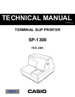
Page 1: ... without price TECHNICAL MANUAL TERMINAL SLIP PRINTER FEB 2000 SP 1300 INDEX ...
Page 20: ... 18 Fig 3 1 Lubricated Areas 1 ...
Page 21: ... 19 Fig 3 2 Lubricated Areas 2 ...
Page 23: ... 21 1 Printer Assembly 1 1 Disassembly Drawing ...
Page 25: ... 23 2 Printer Mechanism 2 1 Disassembly Drawing ...
Page 26: ... 24 ...
Page 30: ... 28 4 Wiring Scheme of Printer ...
Page 31: ... 29 5 Main Logic Board 5 1 Circuit Diagram Main Logic Board 1 5 ...
Page 32: ... 30 Main Logic Board 2 5 ...
Page 33: ... 31 Main Logic Board 3 5 ...
Page 34: ... 32 Main Logic Board 4 5 ...
Page 35: ... 33 Main Logic Board 5 5 ...


