background image

— 13 —

7. Carriage Motor Unit

(1) Remove

Paper detector BD unit according to the
procedure described in Section 2.5

Screw 

1

Ribbon base 

2

Stop ring 

3

Gear 

4

The two soldered lead wires 

5

 with the

soldering iron ( black, red )

Screw 

6

Carriage motor unit 

7

8. Paper Feed Motor Unit

(1) Remove

Printer mechanism unit according to the
procedure described in Section 2.2

Two screws 

1

Paper feed motor unit 

2

Summary of Contents for SP-1300

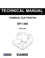
Page 1: ... without price TECHNICAL MANUAL TERMINAL SLIP PRINTER FEB 2000 SP 1300 INDEX ...

Page 2: ...to be executed by service personnel It is not intended for the general user Users of this manual should have a basic knowledge and understanding of the English language This manual is divided into the following sections Chapter 1 Adjustments Chapter 2 Parts Replacement Chapter 3 Maintenance and Lubrication Chapter 4 Parts List First edition Feb 1999 ...

Page 3: ...these adjust ments are maintained whenever the printer is serviced or parts are changed 1 Tools and measures 2 2 Adjusting the gap between the print head and platen 3 2 1 Measuring the gap between the print head and platen 3 2 2 Adjusting the gap between the print head and platen 4 3 Adjusting the dot alignment 5 3 1 Adjustment A 5 3 2 Adjustment B 6 3 3 Adjusting the solenoid gap 7 3 4 Adjusting ...

Page 4: ...ock the screws back into place after completing the processes described in Chapter 1 Adjustments and Chapter 3 Parts Replacement Refer to Fig 4 1 4 2 Tool name Phillips head Screwdriver Wire cutter Tweezers Soldering iron 20W Clearance gauge 0 25mm Clearance gauge 0 30mm Clearance gauge 0 50mm Jig or hexagon wrench 2mm Remarks M2 M4 For removing the stop ring Table 1 1 Tools ...

Page 5: ...mechanism Fig 1 1 Method for measuring the gap Carriage and carriage guide stay backlash Head Removal of the backlash Carriage Platen Gap Fig 1 2 Removal of the carriage and the carriage guide stay backlash 3 Measurements are taken within the left and right printing areas of the platen Measure at 3 to 5 locations while rotating the PF roller Be careful to prevent anything from altering the accurac...

Page 6: ...rotating the adjusting washer D If using a jig make adjustments from above If using a hexagon wrench make adjustments from below Fig 1 3 Adjustments using a jig Fig 1 4 Adjustments using a hexagon wrench Screw 1 Screw 1 Adjusting washer U Adjusting washer D Raising the platen the gap shortens Platen Hexagon wrench 3 When the gap has been adjusted according to the instructions above replace the scr...

Page 7: ...rint generated from right to left is off to the right move the TM sensor board in the direction indicated by the arrow 1 If the print is off to the left move the TM sensor board in the direction indicated by the arrow 2 4 Tighten the screw of the TM sensor board 5 Generate another print sample If the print is still out of alignment go back to step 2 and repeat the above process 6 If the print alig...

Page 8: ...ated in Fig 1 6 refer to the placement of the and symbols Make sure that the and symbols are not aligned If the print generated from right to left is off to the right rotate the motor gear in the direction indi cated by the arrow 3 Return to section 3 1 and repeat Adjustment A Motor gear Idol gear Print generated from left to right outwards H H H H Print generated from right to left inwards H H H ...

Page 9: ...ase in the direction indicated by the arrow to increase the gap to between 0 3 and 0 5 mm Fig 1 7 Adjusting the solenoid gap Screw 1 Solenoid trigger Clutch claw A Claw 0 35 0 5mm 2 This adjustment will cause the end of the solenoid trigger to make contact with the clutch claw A ...

Page 10: ...ding them apart as indicated in Fig 1 5 Adjust the cam horizontally as shown in the illustration while allowing it to make contact with the clutch claw Fig 1 8 Cam Adjustment A Fig 1 9 Cam Adjustment B Cam gear unit Cam Clutch draw B Clutch draw A Solenoid Solenoid trigger Cam Clutch claw A Stop ring ...

Page 11: ...the reverse of disassembly unless otherwise specified 3 After reassembly coat the screw heads with locking sealant 4 Lubrication information is not provided in this chapter Refer to Section 3 2 1 Upper Case Unit 10 2 Printer Mechanism 10 3 Control Panel Board Unit 11 4 Main Logic Board Unit 11 5 Paper Detector BD Unit 12 6 Terminal Board Timing Detector BD Unit 12 7 Carriage Motor Unit 13 8 Paper ...

Page 12: ...cover unit 3 Connector 4 2 Printer Mechanism 1 Remove Upper case unit according to the proce dure described in Section 2 1 Two screws 1 Document table 2 Move the lever down as shown by the arrow in the illustration then pull the document table out to the left Four screws 3 Four rubber sheets 4 Flat cable 5 Three connectors 6 Printer mechanism 7 ...

Page 13: ... proce dure described in Section 2 1 Two screws 1 Control panel board unit 2 4 Main Logic Board Unit 1 Remove Printer mechanism unit according to the procedure described in Section 2 2 Four screws 1 Two tapping screws 2 Two screws DBLC J25SAF 3 Chassis 4 Main logic board 5 ...

Page 14: ...int head drive unit 3 Two screws 4 Ground plate 5 Paper detector BD unit 6 6 Terminal Board Timing Detector BD Unit 1 Remove Paper detector BD unit according to the procedure described in Section 2 5 Three screws 1 Flat cable 2 The two soldered lead wires 3 with the soldering iron black red Terminal board unit 4 Timing detector BD unit 5 ...

Page 15: ... in Section 2 5 Screw 1 Ribbon base 2 Stop ring 3 Gear 4 The two soldered lead wires 5 with the soldering iron black red Screw 6 Carriage motor unit 7 8 Paper Feed Motor Unit 1 Remove Printer mechanism unit according to the procedure described in Section 2 2 Two screws 1 Paper feed motor unit 2 ...

Page 16: ...cable 4 Two tapping screws 5 Ribbon guide 6 WARNING The print head becomes hot after print ing so wait for it to cool before removing it 10 Drive Shaft Unit 1 Remove Print head according to the procedure described in Section 2 9 Two stop rings 1 Gear 2 Carriage guide stay 3 Screw 4 Ribbon shaft guide 5 Two stop rings 6 Idler gear 7 Idler gear 8 9 Stop ring 0 Wave washer A Drive shaft bearing B Dri...

Page 17: ... 15 CHAPTER 3 MAINTENANCE AND LUBRICATION 1 Maintenance 16 1 1 Cleaning 16 1 2 Checks 16 2 Lubrication 17 2 1 Type of oil 17 2 2 Lubrication method 17 2 3 Lubrication locations 17 ...

Page 18: ...ecessary 1 2 Checks Maintenance checks for this printer is divided into the two areas of daily check that the person using the printer carries out during normal use and regular check that can be done only by an experienced person with a knowledge of the equipment 1 Daily check Check that the printer is being properly used Is the ribbon cassette set in the correct position Is the peper set correctl...

Page 19: ...every one million lines Be sure to lubricate equipment after disassembling or replacing parts when oil has been removed by cleaning 2 3 Lubrication locations 1 2 3 4 5 6 7 8 9 10 11 12 13 14 No Holder frame and Support roller shaft Shift frame and Pivot shaft Solenoid base and Trigger assy Clutch spring and Clutch claw Locating lever and Shaft Cam gear unit and Shaft Base frame and Pivot shaft Rib...

Page 20: ... 18 Fig 3 1 Lubricated Areas 1 ...

Page 21: ... 19 Fig 3 2 Lubricated Areas 2 ...

Page 22: ... TY This column shows the number of the part used as indicated in the figure 5 Remarks When differences in specifications exist depending on location destination Note Basically only the parts accompanied by the part number in Parts List can be supplied 1 Printer Assembly 21 1 1 Disassembly Drawing 21 1 2 Parts List for Printer Case 22 2 Printer Mechanism 23 2 1 Disassembly Drawing 23 2 2 Parts Lis...

Page 23: ... 21 1 Printer Assembly 1 1 Disassembly Drawing ...

Page 24: ...E FLAT E4900 560 1 AW C 10 CARTRIDGE INK RIBBON RC200P CBM IR82P 1 NOT SUPPLY X 11 3000 8016 CORE FERRITE TFC 23 11 14 E8038 010 1 AR C 12 9487 0423 CORE FERRITE TFC 16 8 16 E8038 020 1 BK C 13 5560 0368 BAND WIRE T18S E4031 060 2 AA C 14 ADAPTER AC 31AD 31AD 1 NOT SUPPLY X 15 9487 0424 SCREW DBLC J25SAF inch S04991401 2 AG C 16 9487 0425 SCREW TAT3 0 06 0FP S00930603 2 AD C 17 9487 0426 SCREW TAT...

Page 25: ... 23 2 Printer Mechanism 2 1 Disassembly Drawing ...

Page 26: ... 24 ...

Page 27: ...E MP292 1 NOT SUPPLY X 20 GEAR WORM MP2 1 NOT SUPPLY X 21 FRAME B ASSY SHAFT MP290 1 NOT SUPPLY X 22 GEAR MP290 2 NOT SUPPLY X 23 WASHER ADJUSTING U MP290 2 NOT SUPPLY X 24 WASHER ADJUSTING D MP290 2 NOT SUPPLY X 25 PLATEN ASSY MP290 1 NOT SUPPLY X 26 9487 0437 ROLLER PAPER FEED MP290 E8031 090 1 CJ C 27 GEAR PAPER FEED MP290 1 NOT SUPPLY X 28 9487 0438 GEAR IDLE 2 MP290 E8019 140 1 AI C 29 GEAR I...

Page 28: ...AD C 52 9487 0451 RING STOP SE4 0RP S04200016 1 AD C 53 9487 0452 WASHER WAVE DT E8025 090 1 AD C 54 9487 0453 SCREW TAT2 6 05 0FC S00926530 8 AD C 55 9487 0454 SCREW TAT2 6 04 0F S00626404 2 AD C 56 SCREW TAT2 6 05 0FC FL S00926530 2 NOT SUPPLY X 57 9487 0455 SCREW TAT2 6 05 0FSWF S01902622 1 AD C 58 9487 0456 SCREW TAT2 6 16 0FP S01902612 2 AD C 59 TIE WIRE 18UL1007BLK095TT 2 NOT SUPPLY X 60 948...

Page 29: ...T SUPPLY X 7 2 SHEET OPERATION SP290 1 NOT SUPPLY X 7 3 BOARD ASSY CONTROL SP290 1 NOT SUPPLY X 7 4 SCREW TAT3 8PT 2 NOT SUPPLY X Notes Q Quantity per unit R A Essential R Rank B Stock recommended C Others X No stock recommended SPECIFICATION ITEM CODE NO PARTS NAME ...

Page 30: ... 28 4 Wiring Scheme of Printer ...

Page 31: ... 29 5 Main Logic Board 5 1 Circuit Diagram Main Logic Board 1 5 ...

Page 32: ... 30 Main Logic Board 2 5 ...

Page 33: ... 31 Main Logic Board 3 5 ...

Page 34: ... 32 Main Logic Board 4 5 ...

Page 35: ... 33 Main Logic Board 5 5 ...

Page 36: ... CAPACITOR CERAMIC CHIP 0 01UF50V 3 NOT SUPPLY X C81 85 CAPACITOR CHEMICAL 1UF50V 5 NOT SUPPLY X C86 87 CAPACITOR CERAMIC CHIP 0 022UF50V 2 NOT SUPPLY X C88 CAPACITOR CERAMIC CHIP 0 1UF50V 1 NOT SUPPLY X C89 90 NOT MOUNTED NOT SUPPLY X C501 502 CAPACITOR CERAMIC CHIP 0 022UF50V 2 NOT SUPPLY X CN01 CONNECTOR HLEM19S 1 1 NOT SUPPLY X CN02 CONNECTOR 5483 06A RED 1 NOT SUPPLY X CN03 CONNECTOR 5483 02A...

Page 37: ...BK2125 601Y 4 NOT SUPPLY X L05 WIRE JUMPER STP122 1 L 8mmX2 NOT SUPPLY X L21 23 WIRE JUMPER STP122 3 L 5mm NOT SUPPLY X L24 RESISTOR CHIP 0 OHM 1 10W 1 NOT SUPPLY X L25 26 INDICATOR BEADS SBK2125 601Y 2 NOT SUPPLY X L41 47 INDICATOR BEADS SBK2125 601Y 7 NOT SUPPLY X L48 RESISTOR CHIP 0 OHM 1 10W 1 NOT SUPPLY X R001 RESISTOR CHIP 10K OHM 1 10W 1 NOT SUPPLY X R002 RESISTOR CHIP 2 2K OHM 1 10W 1 NOT ...

Page 38: ... NOT SUPPLY X R137 RESISTOR CHIP 4 7K OHM 1 10W 1 NOT SUPPLY X R138 RESISTOR CHIP 10K OHM 1 10W 1 NOT SUPPLY X R139 RESISTOR CHIP 2 7K OHM 1 10W 1 NOT SUPPLY X R140 RESISTOR CHIP 3 3K OHM 1 10W 1 NOT SUPPLY X R151 152 RESISTOR CHIP 330 OHM 1 10W 2 NOT SUPPLY X R153 RESISTOR CHIP 4 7K OHM 1 10W 1 NOT SUPPLY X R154 RESISTOR CHIP 10K OHM 1 10W 1 NOT SUPPLY X R155 RESISTOR CHIP 33K OHM 1 10W 1 NOT SUP...

Page 39: ...15 TRANSISTOR 2SB1359 1 NOT SUPPLY X TR16 TRANSISTOR 2SD2010 1 NOT SUPPLY X TR17 TRANSISTOR CHIP 2SC3875S G AL 1 NOT SUPPLY X TR18 9487 0465 TRANSISTOR 2SB1359 E327 090 1 AS B TR19 22 TRANSISTOR 2SD2010 4 NOT SUPPLY X TR23 TRANSISTOR CHIP 2SC3875S G AL 1 NOT SUPPLY X TR41 TRANSISTOR DIGITAL FN1A4P 1 NOT SUPPLY X TR42 TRANSISTOR DIGITAL FA1A4P 1 NOT SUPPLY X TR43 TRANSISTOR DIGITAL FN1A4P 1 NOT SUP...

Page 40: ... LED1 2 LED GL3KG8 2 NOT SUPPLY X LED3 LED GL3PR8 1 NOT SUPPLY X R1 3 RESISTOR RD 270 1 6W 3 NOT SUPPLY X SW1 3 SWITCH PUSH SKHHAP 3 NOT SUPPLY X Notes Q Quantity per unit R A Essential R Rank B Stock recommended C Others X No stock recommended SPECIFICATION ITEM CODE NO PARTS NAME ...

Page 41: ...CASIO TECHNO CO LTD Overseas Service Division Nishi Shinjuku Kimuraya Bldg 1F 5 25 Nishi Shinjuku 7 Chome Shinjuku ku Tokyo 160 0023 Japan ...

Reviews: