cashco DA8 Installation, Operation & Maintenance Manual Download Page 2

IOM-DA8

2

table  below) before shutting off the process fluid 
supply pressure. If the regulator is specified with 
a fully supported diaphragm, then the diaphragm 
will withstand a loading pressure equal to the 
Diaphragm Proof Rating for the fully supported 
diaphragm.

9.  Upstream Sensing Installation Considerations – 

Internal or External Sensing:
a.  The regulator may be installed with internal or 

external sensing. Unless otherwise specified, 
the regulator is supplied by factory with internal 
sensing. The regulator may be con vert ed in 
the field to external sensing (see Section VII 
Maintenance, Paragraph H).

b.  Reference DA8-TB, Table DAG-12 for recom-

mendations for applying external pressure 
sensing.

c.  For internal sensing, no external line is used.  

For external sensing, use an external control 
line. The line is connected from the port (1/4" 
NPT) on the side of the body di a phragm flange 
to an upstream pressure tap. The pressure 
tap should be located a minimum of 10 pipe 
diameters upstream of the regulator. It is 
recommended that the upstream pressure 
tap be located close to the point of use to 
minimize the adverse affect of variable line 
losses. A tubing outer diameter of 0.25 inch 
is adequate for short sensing lines (less than 
4 feet). Use 3/8" tubing or 1/4" Sch 40 pipe 
for sensing lines of 5 to 50 feet. 

d.  For condensable vapors (i.e. steam) slope 

the external sensing line downward 2 to 5 
de grees to upstream piping to prevent water 
pock ets, which allows the diaphragm chamber 
to always be self draining. The external sens-
ing line may be sloped upward for liquids or 
gases. (i.e., non condensable fluids)

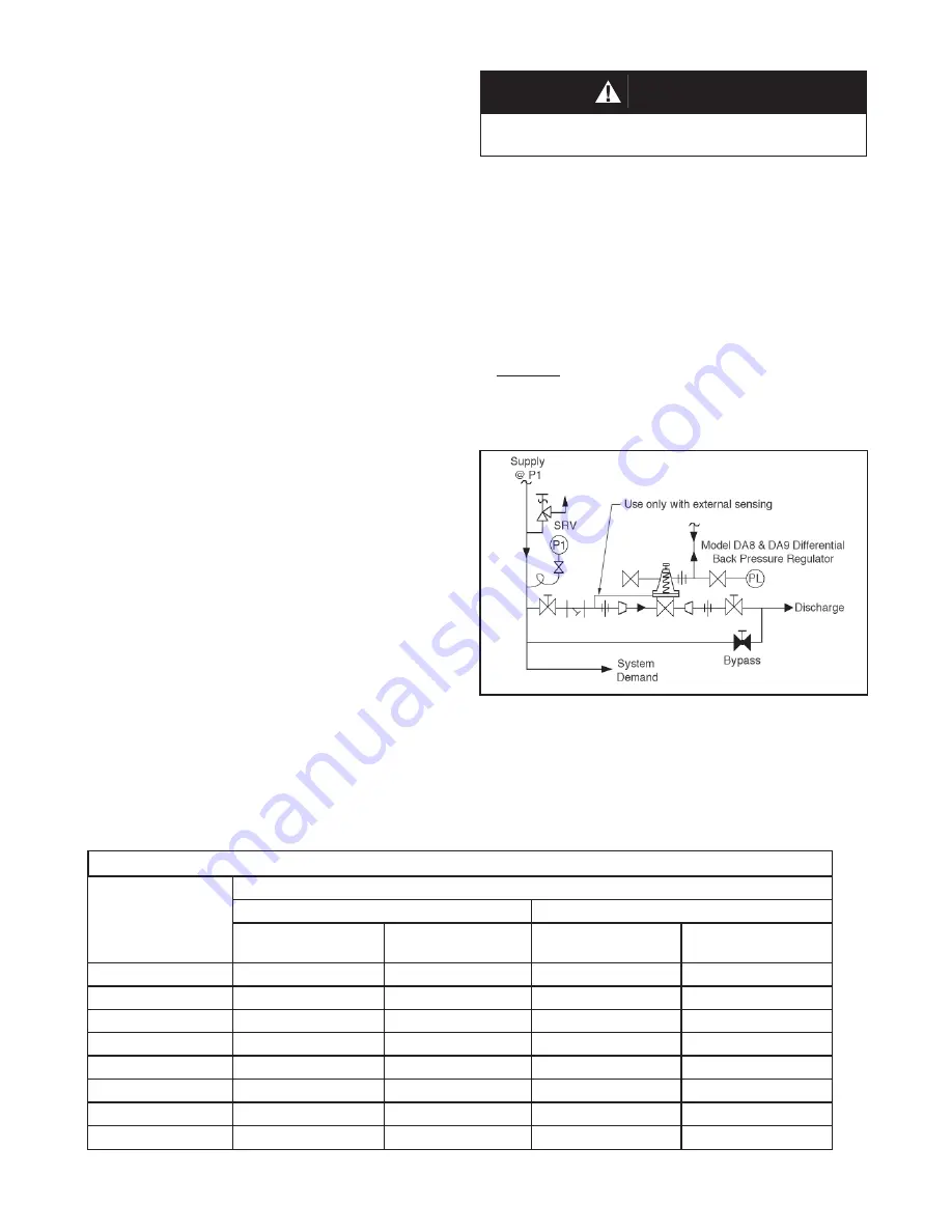
Recommended Piping Schematic for

Differential Back Pressure Station

     CAUTION

The proof test pressure must not exceed the 
diaphragm and body rating for the regulator.

A hydrostatic or pneumatic proof test is allowable un-
der the following conditions for the standard diaphragm 
construction: Uniformly pressurize the valve body inlet, 
valve body outlet, and loading chamber to the lesser of 
the Diaphragm Proof Rating or 1.5 times the Inlet Pres-
sure Rating shown on the nameplate.  For example, a 
1" DA8 with Cast Iron Body and Spring Chamber, Neo-
prene Diaphragm (BC) has an Inlet Pressure Rating of 
400 psig CWP.  The lesser pressure of 1.5X 400 psig = 
600 psig and the BC diaphragm proof rating of 750 psig 
is 

600 psig

.  Therefore, uniformly pressurizing the DA8 

to 600 psig is allowable. Take care to uniformly depres-
surize at end of test.

TABLE 1 – DIAPHRAGM PROOF RATING IN PSIG (BARG)

Diaphragm Material

Body Sizes – inch (mm)

1/2" - 2" (DN15 - 50)

2-1/2" - 4" (DN65 - 100)

Standard Diaphragm

Construction

OPT-81 Full

Diaphragm Support

Standard Diaphragm

Construction

OPT-81 Full

Diaphragm Support

BC, EPR

750 (51.7)

1200 (82.7)

450 (31.0)

800 (55.2)

HK, NBR, HK+TFE

300 (20.7)

1200 (82.7)

225 (15.5)

600 (41.4)

FK

500 (34.5)

1200 (82.7)

225 (15.5)

600 (41.4)

Elastomeric TFE

125 (8.6)

125 (8.6)

125 (8.6)

125 (8.6)

17-7 PH SST

500 (34.5)

1500 (103)

N/A

N/A

Be-Cu

300 (20.7)

750 (51.7)

N/A

N/A

302 SST

350 (24.1)

800 (55.2)

N/A

N/A

Inconel 718

500 (34.5)

1500 (103)

N/A

N/A

Summary of Contents for DA8

Page 1: ...lowed to enter the regulator upon startup 7 FlowDirection Installsotheflowdirectionmatches the arrow cast on the body or other markings such as in and out 8 PrecautionforStandardDiaphragmConstruction...

Page 2: ...m piping to prevent water pockets whichallowsthediaphragmchamber to always be self draining The external sens ing line may be sloped upward for liquids or gases i e non condensable fluids Recommended...

Page 3: ...o not walk away and leave a bypassed regulator unattended 5 Slowly open the inlet upstream block valve to about 25 open observing the inlet upstream pressure gauge Determine if the regulator is flowin...

Page 4: ...or repairing regulators 4 Owner should refer to owner s procedures for removal handling cleaning and disposal of nonreusable parts i e gaskets etc NOTE On regulators originally supplied as SpecialClea...

Page 5: ...Figure 1 Dynamic Side Seals Type CP TFE Cap Dynamic Seal Type PR PRA Dynamic Seal Type UC U Cup Dynamic Seal Type NO No Dynamic Seal NOTE Two separate piston rings per assembly Standard Flow Only 1 1...

Page 6: ...removed metal parts C Disassembly of the ITA 1 Body Sizes 1 2 2 See Figures 2 through 4 a Obtain two pieces of square section barstock with a 3 8 7 16 dimension approximately 2 inches long b Place pl...

Page 7: ...rts should be free of surface contaminants burrs oxides and scale Rework and clean the parts as necessary Surface conditions thataffecttheregulatorperformancearestated below replace parts that can not...

Page 8: ...seal 27 1 edgetouchestheupperlipofthecage 19 While gently applying force to press the piston guide bushing 13 or valve plug 20 into the cage 19 simultaneously use fingers to lightly press the cap sea...

Page 9: ...agm construction place compatible gasket sealant on both sides and place new lower pusher plate gasket 14 4 on over upper end of valve plug 20 and onto lower diaphragm pusher plate 10 Gasket sealant i...

Page 10: ...ck off range spring assembly a fraction of the turntoalignthemilledslotsperpendicular to the center line of the valve body The slots should now be ready to accept the internal ribs of the spring chamb...

Page 11: ...kage a Determine test pressure If upper value of range spring is less than 55 psig use test pressure of 5 psig less than upper value of range spring If upper value of range spring is greater than 55 p...

Page 12: ...t regulator outlet as close as possible to outlet port etc Following are some of the more common complaints along with possible causes and remedies SECTION VIII Possible Causes Remedies A Sticking of...

Page 13: ...contains trim replacement parts plus seal s diaphragm s and gasket s Step 3 Contact your local KM Sales Representative and specify the product code number along with a description of any parts not in...

Page 14: ...IOM DA8 14 Figure 2 Composition Diaphragm FTO Reverse Flow Direction...

Page 15: ...Cage Seal 18 Cage Cap Screws Item No Description 19 Cage 20 Valve Plug 21 Lower Cage Gasket 23 Body 24 Lower Guide Bushing 26 Tap Plug Not Shown 27 Dynamic Side Seal 27 1 TFE Cap Seal 27 2 O ring Ener...

Page 16: ...are presented for informational purposes only and while every effort has been made to ensure their accuracy they are not to be con strued as warranties or guarantees express or implied regarding the p...

Page 17: ...The details of the assessment in terms of the individual Essential Health and Safety Requirements are listed in Table 1 Table 2 lists all of the models and options that were evaluated and along with...

Page 18: ...e same requirements for the piping system Also see item 30 in Table 1 2 The system designer and users must take precautions to prevent rapid system pressurization which may raise surface temperatures...

Reviews: