9
K
ey
L
argo
™
II
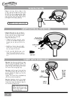
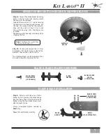
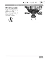
Step 11a.
Line up the two clearance holes
in the cap with the two threaded holes
on the raised rim of the switch housing.
Press the cap onto the switch housing to
seat the guide pins into the alignment
holes of the switch housing.
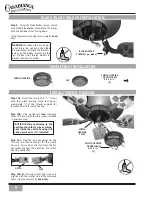
Step 11b.
Using the two (2) 8-32 X
3
/
8
”
screws removed in Step 9, install the cap
onto the switch housing.
Tighten securely by
hand
only.
INSTALLINg THE SWITCH HOUSINg CAp

