background image

4

gETTINg STARTED

Installing a New Ceiling Fixture Outlet Box

If you do not have an existing fixture located where you wish 

to  place  your  Casablanca  fan,  an  approved  ceiling  fixture 

outlet box must be installed and wired.

Using Existing Ceiling Fixture Outlet Box

After  turning  the  power  OFF  at  its  source  (either  circuit 

breaker or fuse box), lower the old fixture and disconnect 

the wiring. Check the ceiling fixture outlet box to be sure 

that it is marked ‘

Approved for ceiling fan mounting

’. If it is 

not, a new box must be installed. 

warning: To reduce the risk of fire, electrical shock, 

or personal injury, mount to outlet box marked ac-

ceptable for ceiling fan support using the mounting 

hardware provided with the outlet box.

noTe:

 The fan weight is 33 pounds.

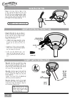
CROSSBAR mOUNTINg BRACKET INSTALLATION

JOIST

CEILINg

WIRINg

CROSSBAR 

mOUNTINg 

BRACKET

FLAT

WASHER

gREEN

gROUND

WIRE

CEILINg FAN

AppROVED

WIRINg BOX

RIDgE

SIDE

DOWN

AppROVED 

OUTLET BOX

HARDWARE

note:

 After removing the old fixture, check the outlet box 

to insure that it is supported by a joist or beam across its 

upper surface. If not, a 2” x 4” stud must be installed.

Step 1a.

 Remove the knockout plug in the center of the out-

let box or drill a 

1

/

2

 hole for the lag screw to pass through. 

Then drill a 

1

/

4

 guide hole into the joist or beam to a depth 

of 3

.

Step 1b.

 Route the outlet box wires through the keyhole slot of 

the crossbar mounting bracket as shown. Attach the crossbar 

mounting bracket to outlet box with screws provided, assuring 

that the outlet box wires are not pinched by the washer. 

CAUTION: To reduce the risk of personal injury, 

use only the mounting hardware provided with 

the approved outlet box to install the crossbar 

mounting bracket.

CEILINg HARDWARE & SUppORT INSTALATION pARTS

CROSSBAR mOUNT-

INg BRACKET

WIRE NUT (4)

addiTional hardware

LAg SCREW 

3

/

8

” #7 X 5” (1)

WARNINg!

SUppORT DIRECTLY TO

BUILDINg STRUCTURE ONLY.

1” x 8-32 ROUNDED 

HEAD SCREW (2)

FLAT WASHER (2)

2

7

/

16

” x 8-32 ROUNDED 

HEAD SCREW (2)

Summary of Contents for Key Largo II

Page 1: ...r best performance and for your warranty to be valid use only genuine Casablanca blades light fixtures and accessories Safety and the proper operation of your Casablanca fan both require a thorough kn...

Page 2: ...imum of 7 above the floor Do not locate the fan in a doorway or above a swinging door In any installation the tips of the blades must be at least 18 from the wall in order to provide sufficient cleara...

Page 3: ...tion of the downrod Thread the downrod into the motor coupling until it stops turning this will take at least four and a half full turns Step C Securely tighten the set screw with the provided allen w...

Page 4: ...fan approved wiring box ridge side down approved outlet box hardware Note After removing the old fixture check the outlet box to insure that it is supported by a joist or beam across its upper surfac...

Page 5: ...let box be of sufficient capacity enabling it to support the weight of fan and light fixture under any conditions lag screw LAG SCREW INSTALLATION CANOPY CANOPY HATCH CANOPY HARDWARE CANOPY INSTALLATI...

Page 6: ...the fan body until the slot in the ball fits into the pin opposite the canopy opening slot ball BLACK BLUE D1 OPTION WIRES 2 NOTE The fan weight is 33 pounds pin CANOPY HATCH INSTALLATION Step 6a Tuc...

Page 7: ...n Step 10 Step 7b Unscrew and remove the 10 ship ping blocks Put the ten screws aside for the moment they will be used in Step 8 The shipping blocks can be discarded they are used only when shipping t...

Page 8: ...blade brackets when installing the brackets balancing the blades or cleaning the fan Do not insert foreign objects in etween rotation fan blades Step 10b Line up the two inner clearance holes in the c...

Page 9: ...ised rim of the switch housing Press the cap onto the switch housing to seat the guide pins into the alignment holes of the switch housing Step 11b Using the two 2 8 32 X 3 8 screws removed in Step 9...

Page 10: ...LIGHT PULL CHAIN SWITCH REVERSE SWITCH FAN SPEED CON TROL PULL CHAIN SWITCH 4 SPEED OPERATION 4 SPEED OPTIONAL WALL CONTROL W 24 SOLD SEPARATELY 4 SPEED OPTIONAL WALL CONTROL W 28 SOLD SEPARATELY 4 S...

Page 11: ...terference and 2 this device must accept any interference including interference that may cause undesired operation of the device 1 This device complies with part 15 of the FCC Rules Operation is subj...

Reviews: