


Reference Manual V1.10
Software Versions 3.xx
X300-621-110
Page 59
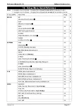
19.
Glossary Terms
Term
Definition
COMM
The communications protocol used to communicate with the R300 Series
Count-by
The smallest change in weight units that the display can show. See also
Resolution.
Division
A single graduation.
EEPROM
Electrically Erasable Programmable Read-Only Memory
EMC
Electro-Magnetic Compatibility Regulation
FIR
Finite Impulse Response
Full Scale
The maximum gross weight allowed on the scale. This is used to detect
overload and underload conditions, etc.
Graduations
The maximum number of display steps between zero gross load and full
capacity gross load. It is equal to the full scale divided by the resolution.
LED
Light Emitting Diode
NTEP
National Type Evaluation Program
OIML
International Organization of Legal Metrology
opto-LINK Cable opto-isolated infrared communications link cable
PLC
Programmable Logic Controller
Range
Total change in weight between zero gross load and full capacity gross load (ie.
the nominated total capacity of the scale). It is always given in displayed weight
units.
Resolution
The smallest change in weight units that the display can show. See also Count-
by.
RFI
Radio Frequency Interference
Ring Network
A network of up to 31 Instruments connected to a central computer
RS-232
Standard for communications hardware layers.
Step-Response
The step-response is the time between placing a weight on the scale and the
correct weight reading being displayed.
Transients
A temporary voltage oscillation or spike caused by a sudden change of load (or
other external influence).
Units
The actual units of measurement (kilograms, tonnes, pounds, etc.).
19.1. List of Figures
Figure 1: Weight Indicator ............................................................................................................... 4
Figure 2: Cable Connections ........................................................................................................... 8
Figure 3: 4-Wire Connections ......................................................................................................... 9
Figure 4: 6-Wire Connections ......................................................................................................... 9
Figure 5: RS-232
– One Instrument to PC using COM Port (DB9) ................................................ 10
Figure 6: RS-232
– One Instrument to PC using COM Port (DB25) .............................................. 10
Figure 7: RS-232 Short Cable Runs: Ring Network using COM Port (DB9) .................................. 11
Figure 8: RS-232 Long Cable Runs: Ring Network using COM Port (DB9) ................................... 12
Figure 9: RS-232
– Instrument to Printer (DB25)........................................................................... 13
Figure 10: Remote Input ............................................................................................................... 13