CAS 1560A User Manual Download Page 10

21

20

SET MODE

1. How to enter

Turn on the power while pressing the 

TARE

 key on the front of the indicator.
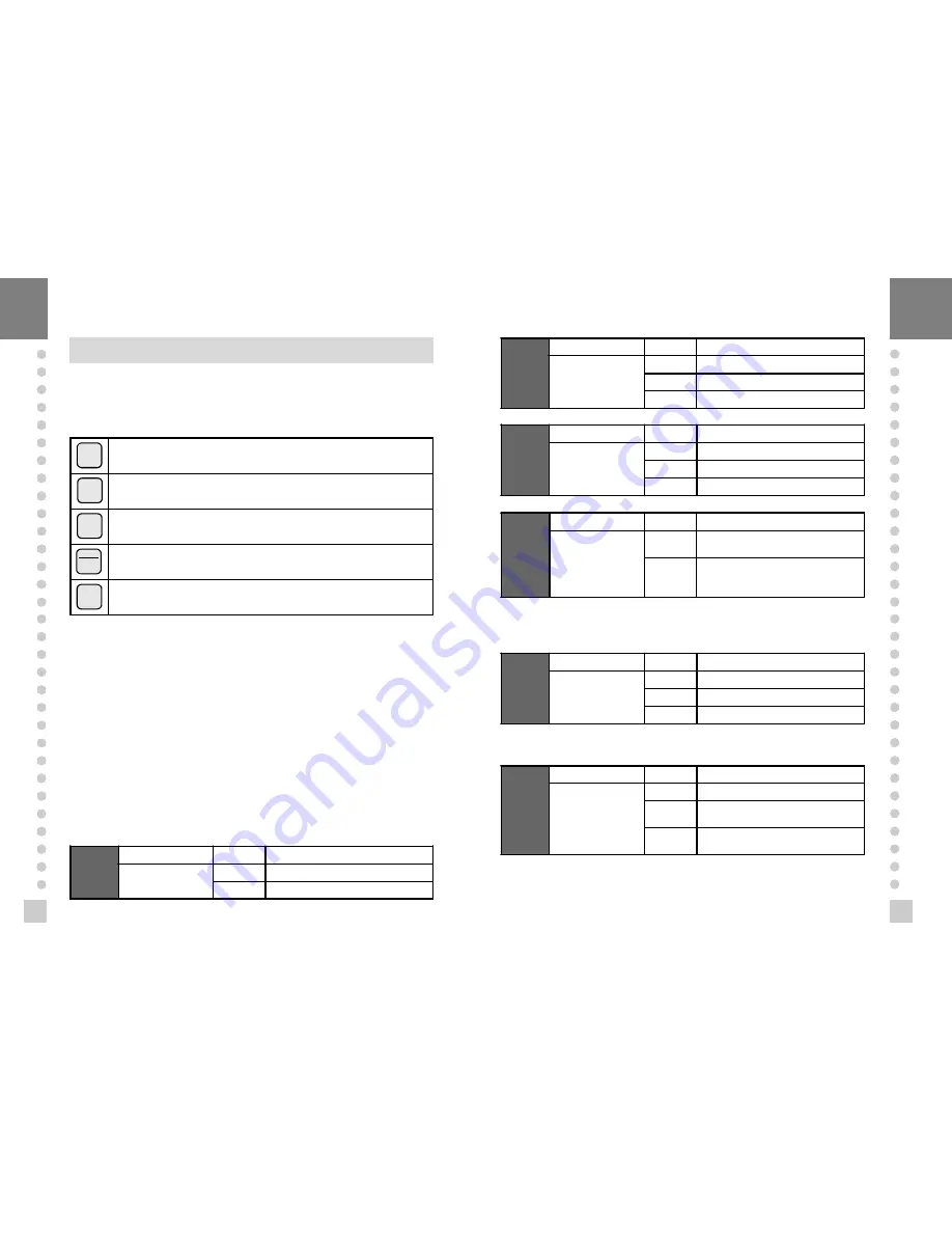
2. Available keys

 used to save inputted value and exit to menu selection.

 used to set the current value to zero

 used to set the current value x10.

 used to set the current value +1.

 used to set the current value -1.

3. Set Value Conversion Menu

F01   Change of display unit
F02   

SET

 Key usage

F03   Serial port Usage
F04   Auto Print Usage
F05   Speed control  of weigh display
F06   Automatic zero condition set
F07   Weight backup function set
F08   External Input 2 Usage
F09   

ZERO

 key operation range set

F10   Device number
F11   Baud rate set
F12   Data set sent to Computer
F13   Hold type set
F14   Set Clock
F20   Relay mode (CI-1560A)

F01

Function

Display

Description

SET display

unit(0~1)

F01  0

Unit : kg

F01  1

Unit : ton

F02

Function

Display

Description

SET key usage(0~2)

F02  0

  is Hold key

F02  1   is Total data print

F02  2

  is Start key in relay mode

F03

Function

Display

Description

Serial Port usage

(0~2)

F03  0

 Not Used

F03  1  Connection to Serial Printer

F03  2

 Connection to P.C or RemoteDisplay

F04

Function

Display

Description

Automatic print(0~1)

F04  0

 Manual print-whenever you press

 the key, it will be printed.

F04  1

 Automatic print-when the weight is

 stable or you press the key, it will be
 printed.

F05

Function

Display

Description

Speed control of
weighing display

(Digial filter function,

1~9)

F05  1  In high speed

F05  5

 In normal speed

F05  9

 Very slowly

4

Note 1. Upon setting the automatic print, the print is carried out without

                 pressing the print key when the weight is in stable state.
    Note 2. It shall be in 1 of F03.

4

Note . Adjust the speed variation of the weight on the screen to be suitable

               for the current usage.

F06

Function

Display

Description

Automatic zero

condition set(0~9)

F06  0

 No compensation

F06  2

 Compensation for gradual change

 below two division for 3 seconds.

F06  9

 Compensation for gradual change

 below nine division for 3 sec.

TARE

3

NET

GROSS

5

3

PRINT

SET

ZERO

Summary of Contents for 1560A

Page 1: ...N 6 FEATURES 6 TECHNICAL SPECIFICATION 7 MEASURE OF APPEARANCE 8 FRONT PANEL 9 REARPANEL 10 INSTALLATION CONNECTION 11 TESTMODE 13 CALIBRATIONMODE 16 SETMODE 20 WEIGHINGMODE 28 RS 232CINTERFACE CLOCK 32 ERROR MESSAGEAND TROUBLESHOOTING 36 ...

Page 2: ...den temperature changes n This scale must be installed in a dry and liquid free environment n Do not severely press because the light pressing of keys can incite the operation n Do not use inflammable materials in cleaning n Keep the scale away from strong EMI noises may cause incorrect weight reading ...

Page 3: ... power failure n Adjustable display rate Digital filter function n Tare weight setting with keys n Users can set maximum weight which users want to and division at one s disposal n Self test hardware function n Independent zero calibration n External Input Output CI 1560A 2 External Input zero F08 4 External Output zero 1 Step 2 Step Final n Serial printer connection n Print date and time by inner...

Page 4: ...n this key is pressed the scale stores current weight as the tareweight If you press TARE key in unload condition tare setting is released Used to enter the SET mode Used to current value X 10 in CAL SET mode Use this key to switch from GROSS to NET weight The annunciators and display will alternate between GROSS and NET aswell In case tare weight is REGISTERED tare plus item s weight is GROSS wei...

Page 5: ...ield n Connecting method 4Each L C manufacturer sor model s wire color could be different In that case please note the following diagram n Manufacturer s wire color Connector Company Pin 1 EX Pin 3 EX Pin 5 SIG Pin 6 SIG Pin 7 SHIELD CAS RED WHITE GREEN BLUE CASE KYOWA RED BLACK GREEN WHITE CASE INTERFACE RED BLACK GREEN WHITE CASE P T RED BLACK GREEN WHITE CASE BLS GREEN BLACK WHITE RED YELLOW SH...

Page 6: ...COM KEY IN PUT COM TEST MODE n How to enter Turn on the power while pressing the ZERO key on the front of the indicator 4When test is done Press SET key n Available keys Set key Used for moving to the next test menu Other keys Used for changing the preset value n Test Menu TEST 1 TEST 6 TEST 1 Key test TEST 2 Display test TEST 3 Load cell test and A D conversion test TEST 4 Serial interface test T...

Page 7: ...ode and F03 is 2 in SET mode KEY DISPLAY DESCRIPTION SET to next menu Other keys Transmitting key Waiting for transmission and reception Transmitted none Received 1 Transmitted 1 Received none Transmitted 1 Received 1 INDICATOR TEST When it isn t connected with PC Conect directly between No 2 TXD and No 3 RXD in indicator of serial port If transmitting data is identical with receiving data by pres...

Page 8: ...n Menu CAL 1 CAL 7 CAL 1 Maximum Capacity Set CAL 2 Minimum Division Set CAL 3 Setting Weight in Span Calibration CAL 4 Zero Calibration CAL 5 Span Calibration CAL 1 n FUNCTION Maximum Capacity Set RANGE 8 1 999 999 KEY DISPLAY DESCRIPTION SET key store and into next menu ZERO key change the set value t1 00 CAL 1 Maximum capacity value ex 5000 Program version CAL 1 condition 5000 kg 4Note 1 The ma...

Page 9: ...m moves into CAL 5 automatically Note 2 If the zero value is too low ERROR message ERR 27 is displayed Note 3 If the zero value is too high ERROR message ERR 26 is displayed Note 4 Zero calibration can be done independently If you press ZERO key instead of SET key zero calibration will perform CAL 5 n FUNCTION Span Calibration 4Note 1 If Span calibration is done without any error GOOD message is d...

Page 10: ...al data print F02 2 is Start key in relay mode F03 Function Display Description Serial Port usage 0 2 F03 0 Not Used F03 1 Connection to Serial Printer F03 2 Connection to P C or RemoteDisplay F04 Function Display Description Automatic print 0 1 F04 0 Manual print whenever you press the key it will be printed F04 1 Automatic print when the weight is stable or you press the key it will be printed F...

Page 11: ...evice No 00 F10 05 Device No 05 4Note 1 This device number is the data demanding signal in serial communication Note 2 It shall be in 2 in F03 F11 Function Display Description Baud rate Unit of speed In data transmission 0 5 F11 0 600bps bit per second F11 1 1200bps F11 2 2400bps F11 3 4800bps F11 4 9600bps F11 5 19200bps 4Note It shall be just in 2 of F03 F12 Function Display Description Data set...

Page 12: ...y 00 12 C2 10 October C3 Function Display Description Set Day 00 31 C3 30 Day 30 C4 Function Display Description Set Hour 00 23 C4 15 P M 3 C5 Function Display Description Set Minute 00 59 C5 59 Minute 59 C6 Function Display Description Set Second 00 59 C6 39 Second 39 F20 Function Display Description RELAY MODE USAGE 0 4 F20 0 Not used F20 1 Limit Mode F20 2 Checker Mode F20 3 Limit type Chcker M...

Page 13: ...Low limit relay will come ON Weight Lo L FALL High limit relay will come ON Weight HI H FALL n Checker Mode LOW limit HIGH limit 0 kg 50 kg 100 kg WEIGHT RELAY ON OFF ON OFF ON OFF ON OFF ZERO OUT RELAY 1 LOW OUT RELAY 2 HIGH OUT RELAY 3 FINAL OUT RELAY 4 n Limit Type Checker Mode n Paker Mode LOW limit HIGH limit 0 kg 50 kg 100 kg WEIGHT RELAY ZERO OUT RELAY 1 LOW OUT RELAY 2 HIGH OUT RELAY 3 FIN...

Page 14: ...ompensation Display or Key On platform Description step 1 Empty Zero point drift step 2 Press ZERO key when the weight is stable step 3 Empty ZERO Compensation The present value is returned the display to the ZERO 4Note 1 It shall be in zero range to 4 or 10 of maximum capacity in Set Menu of F09 Note 2 Non ability in HOLD state of the weight Note 3 Non ability in setting tare n Example 2 Tare Fun...

Page 15: ...g condition HOLD will release step 5 Unload When it is became unloading condition HOLD will release automatically 4Note 1 Choose HOLD type in SET menu F13 Average HOLD F13 0 Compute the average weight of oscillating weights Peak HOLD F13 1 Choose the maximum weight among oscillating weights Sampling HOLD F13 2 Choose the current weight of oscillating weights Note 2 In case of using external input ...

Page 16: ... over load GS gross NT net Device ID Lampstatus byte Blank Simple communication program BASIC 10 OPEN COM1 9600 N 8 1 As 1 20 IF LOC 1 0 THEN 60 30 A INPUT 1 1 40 PRINT A 50 GO TO 20 60 B IN KEY IF B THEN 20 70 PRINT B 80 PRINT 1 B 90 GO TO 20 Simple communication program C include bios h include conio h define COM1 0 define DATA_READY 0x100 define TRUE 1 define FALSE 0 define SETTINGS 0x80 0x03 0...

Page 17: ... Male RS 232C port of CI 1560A 9 pin port Female Serial port of computer n Sub display connection RXD 3 ㅇ TXD 2 ㅇ GND 7 ㅇ ㅇ 2 Transmit Data ㅇ 3 Receive Data ㅇ 7 Signal Ground 9 pin port Male RS 232C port of CI 1500A 9 pin port Male RS 232C port of sub display RXD 3 ㅇ TXD 2 ㅇ GND 7 ㅇ ㅇ 9 Transmit Data ㅇ 5 Receive Data ㅇ 1 Signal Ground n CAS TOP printer connection P 202 9 pin port Male RS 232C port...

Page 18: ...OUBLE SHOOTING 1 In Weighing Mode ERR 02 n Reason Load cell connection failure or error in A D conversion part n Trouble shooting Check the Load Cell connector to see if the polarity of signal is reversed ERR 13 n Reason Zero range deviate from the set range n Trouble shooting Confirm that there is nothing on the weighing platform If nothing exist do Calibration in CAL mode ERR 22 n Reason Setting...

Reviews: