


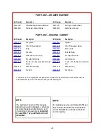

9
HOLDING CABINET NORMAL OPERATION
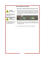
CAUTION:
HOT SURFACE
Inner surfaces of the unit
will be very hot during and
after operation.
Avoid touching the cabinet
when loading or removing
product.
First Use
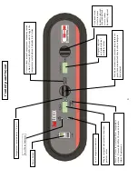
Turn the cabinet on using the power switch located on the far left side of the
control panel. The control display will illuminate.
When the cabinet is first turned on, the temperature display will show the
current hardware / software revision, for example: “r26”. Then display will
then alternately flash “PrE” and the set point values.
To adjust the temperature or humidity setting, rotate the respective dial to
the desired set point and stop. After 3 seconds, if either setting is adjusted,
the newly adjusted value will be stored in the controllers memory. If the cabi-
net power is interrupted, the last value set will be the new value restored
upon power being restored.
It will take approximately 30 minutes for the cabinet to warm up to a factory
default setting of 160ºF (71
°
C). Once the set point is reached, a short alarm
burst will be heard to indicate that the cabinet has reached the set point.
Humidity system
This holding cabinet is equipped with a water reservoir and automatic fill
system (standard) that can be used to humidify the cabinet. The reservoir
will not automatically begin to fill until the lowest water level probe is sub-
merged. This is a safety feature that will prevent the automatic fill system
from operating if the reservoir has been removed.
To activate the auto fill system, the reservoir must be primed. Ensure that
water line is connected to the cabinet (upper end on left side of cabinet).
Pour potable water into the reservoir until the water touches the lowest level
probe. Once the lowest probe is in water, the fill valve will turn on and the
reservoir will begin to fill. Once the highest level probe senses water, the fill
solenoid will turn off.
Due to the differences in water supply conditions, it may be necessary to
calibrate the cabinet to properly sense your water supply. Please see pages
7-8 for the calibration procedures.
As the unit maintains the desired humidity level, water will be used from the
reservoir. When the water level drops below the low level probe, the fill sole-
noid will turn on again thus repeating the cycle. The holding cabinet is
equipped with a low water alarm, see the following page for details on the
alarm system.
Although the cabinet is equipped with an auto fill system, it is not necessary
to have the cabinet coupled to a water supply line. The reservoir can be
filled manually. As long as the low level probe is in contact with water, the
control can maintain the desired humidity setting.
Humidity settings at high levels will cause condensation to collect in the cab-
inet. A removable condensation pan is located under the base of the cabi-
net to collect excess water. Check periodically and empty when full.
Factory default setpoints:
- temperature: 160ºF (71
°
C)
- humidity: 50%
- low temp alarm:140ºF(60
°
C)
Operating ranges:
- temp alarm: 80ºF-180ºF
(27-82ºC)
- air temp: 90ºF-200ºF
(32-93ºC)
- humidity: OFF-90%
The factory default for the
temperature display is in ºF.
To change the display to
read in ºC, push in and hold
the view actual button for 10
seconds. The display will
now read in ºC.
To change the display temp
back to ºF, repeat the same
procedure above.
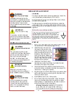
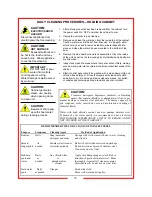
CAUTION:
STEAM HAZARD
This unit produces steam,
use caution when cleaning
or opening the doors.
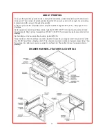
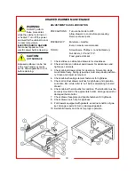
MANUAL FILL OF WATER RESERVOIR
Water reservoir located at top left of cabinet interior. To fill, pull out metal
frame with pan. IF CABINET IS HOT, USE OVEN MITTS AND PROCEED
WITH CAUTION—FRAME AND WATER WILL BE HOT.
To remove, pull out metal frame. DO NOT REMOVE IF CABINET OR WA-
TER IS HOT. ALLOW CABINET TO COOL COMPLETELY. While holding
metal frame, slide pan to rear and then lower to clear the frame. To install,
reverse procedure.


