background image

INSTALLATION and STARTUP 


LOCATION 


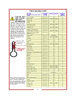
For proper operation and maximum performance, locate the 
unit in an ambient air temperature of 70ºF (21ºC).   


Avoid placement in areas near exhaust fans or where there 
are active air movements.   


For safe operation and maximum performance, locate the 
unit at least 2” from any wall or combustible material. Avoid 
storing flammable or combustible materials in, on or near the 
appliance.


Unit must be on a solid level surface. 

INSTALLATION and START-UP 


If necessary, contact a licensed 
electrician to install an appropriate 
30 amp electrical circuit with correct 
NEMA receptacle.   
 

DO NOT use an extension cord. 

Installation procedures must be  
performed by a qualified technician 
with full knowledge of all applicable 
electrical codes.  Failure could   
result in personal injury and proper-
ty damage. 


Damage to unit due to being      
connected to the wrong voltage or 
phase is 

NOT 

covered by warranty. 

START-UP 


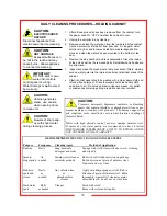
1.  Prior to use, thoroughly clean the interior of the unit, per 

the instructions in this manual (pages 15-16). 

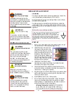
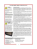
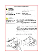
2.  Install the water reservoir into 

the frame at the top left of the 
cabinet. Place the pan over the 
element towards the rear of the 
assembly, then slide pan for-
ward into the frame. Make sure 
the element hangs down inside 
the pan. Slide the entire assem-
bly back into the cabinet. 

3.  Install the 12”x20”x2.5” stain-

less steel pan under the cabinet. It will slide into rails 
mounted to the base of the cabinet. 

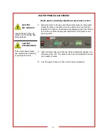
4.  If automatic water fill is desired, connect water line to 

connection at top on left side of cabinet. (see page 9 for 
instructions on priming the system) 

5.  Plug the power cord of the cabinet into a grounded outlet 

with a electrical service according to the electrical infor-
mation provided at right. 

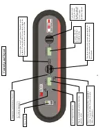
6.  Set POWER switch to the “ON” position. 

7.  Do not load product into the cabinet.  Allow the heat to 

remove any residual oils which may adhere to inside 
metal surfaces.  A slight emission of smoke is common 
during the first few hours of operation. 

T

he ground prong of the power 

cord is part of a system designed to 
protect you from electric shock in 
the event of internal damage. 


DO NOT cut off the large round 
ground prong or twist a blade to fit 
an existing receptacle. 

CAUTION:


Electrical Shock Hazard 


Unit is not waterproof, to avoid   
electrical shock, keep unit and 
counter from being submerged in 
water.  Do not operate if unit has 
been in contact with water. 

IMPORTANT:  

Power cord is 10' long  

IMPORTANT: 
Not under warranty 

WARNING: 

Risk of personal injury 

WARNING: 

Risk of personal injury 


To prevent an electrical shock hazard between the appliance 
and other appliances or metal parts in close vicinity, an 
equalization-bonding stud is provided. An equalization bond-
ing lead must be connected to this stud and the other appli-
ances/metal parts to provide sufficient protection against 
potential difference. The terminal is marked with the following 
symbol: 

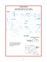
Electrical Information: 

operates on 120 volts, 60 

cycle, 2900 watts, 24.2 amps. NEMA 5-30P plug. 
Ten foot rubber cord with 3-prong grounding plug 

Summary of Contents for HL10-10-RW

Page 1: ...MAINTENANCE 17 18 WIRING DIAGRAM 19 TROUBLESHOOTING GUIDE 20 WARRANTY STATEMENT 21 MANUFACTURED BY CARTER HOFFMANN 1551 McCormick Avenue Mundelein IL 60060 U S A Phone 847 362 5500 Fax 847 367 8981 To...

Page 2: ...ose as described in the manual a This equipment is specifically designed to hold pre cooked food at temperature b This equipment is intended for use in commercial establishments only c This equipment...

Page 3: ...6 pans Two drawer warmer built into bottom of unit accommodates 12 x20 steam table pans up to 6 deep end loaded Wells Mfg Model RWN 26 Individual thermostatic temperature control for each drawer with...

Page 4: ...to support your claim GROUNDING INSTRUCTIONS This appliance is equipped with a cord having a grounding wire with a grounding plug which must be plugged into an outlet that is properly installed and gr...

Page 5: ...he base of the cabinet 4 If automatic water fill is desired connect water line to connection at top on left side of cabinet see page 9 for instructions on priming the system 5 Plug the power cord of t...

Page 6: ...Turn knob clockwise to increase temperature set point turn counterclockwise to reduce tempera ture setpoint Press to show actual Temperature Humidity inside cabinet Press and hold for 10 seconds to to...

Page 7: ...the left on the temperature display moves from the bottom to the top of the display see illustration below This probe is now sensing the water 5 Add more water to the pan until the middle length prob...

Page 8: ...o the top of the display see illustration This probe is now sensing water 7 When all three lines are at the top of the temperature display turn off power to the unit The water probes are now adjusted...

Page 9: ...st level probe senses water the fill solenoid will turn off Due to the differences in water supply conditions it may be necessary to calibrate the cabinet to properly sense your water supply Please se...

Page 10: ...en water drops below the low level probe the control cuts power to the heating element used to produce steam If the water level is below the low probe for more than 5 minutes an audible alarm will sou...

Page 11: ...r in structions Set temperature to desired proof temperature typically 85 98 F 30 37 C for most sweet yeast and bread dough products Note set lower temperature of 78 84 F 26 29 C for croissant dough t...

Page 12: ...directly into the empty i e no water drawer pan 3 MOIST HEAT WITH OPTIONAL HUMITROL RACK A To set for MOIST OPERATION remove the Humitrol Rack from the bottomof the drawer insert pan and carefully pou...

Page 13: ...st operation DO NOT Put ice into a warmer pan Ice in the pan will cause condensation on the inside of the warmer cavity NOTE The chart below is intended as a guide only Your own experience with this a...

Page 14: ...75 F 79 C 75 60 Pastries 165 F 74 C 20 30 Pizza uncovered 180 F 82 C 10 30 Pizza boxed 180 F 82 C NONE REQUIRED 60 Poppers Deep Fried 190 F 88 C NONE REQUIRED 25 Poultry Whole bone in 175 F 79 C 55 60...

Page 15: ...el cleaner Rub with soft cloth as directed on package Fingerprints needed or similar products Rub in direction of grain of stainless steel Do not use on vinyl trim Stubborn Daily Any chloride free App...

Page 16: ...our water into controls control panel or wiring Water damage is not covered by warranty CAUTION Beware of sharp edges with sheet metal during cleaning process 2 Clean drawers drawer pans Humitrol rack...

Page 17: ...REMOVE THE SCREWS THAT HOLD THE HINGES TO THE DOOR Remove the door tak ing care not to let it fall 2 Remove the door strike plate and screws adjacent to the door opening on the cabinet Reinstall door...

Page 18: ...et and drawers for cleanliness 2 Check all rollers on cabinet and drawers for cleanliness and tightness Lubricate 3 Check cabinet drawer stops for operation Non spring stops must rotate freely Spring...

Page 19: ...GITAL CONTROL 120 VOLT 2900 WATT 24 2 AMP 1 PH 60 HZ 19 WIRING DIAGRAM Cabinet Drawer Warmer Note Drawer warmer and cabinet joined in box and wired to main power of the cabinet creating independent ci...

Page 20: ...LIST HOLDING CABINET Part Number Description Part Number Description 17020 2214 Door gasket 18600 0046 High limit 18612 0315 120v 1000w air element 18612 0393 120v 1000w water element 18614 0291 Motor...

Page 21: ...nal wiring error Call service technician Circulation motor has quit Call service technician Improper voltage Call service technician to verify incoming voltage matches cabinet specifications No lights...

Page 22: ...CARTER HOFFMANN to be defective CARTER HOFFMANN neither makes nor assumes and does not authorize any other person to make or assume any obligation or liability in connection with its products other th...

Reviews: