background image

9

Generating Reports — 

Reports can be generated dur-

ing the Quick Configure (if the box was checked) or can be
generated at any time using menu commands. Two types of re-
ports can be generated. Information in each report can be
cleared separately. Both reports generate text (.txt) files. The
default location for reports is C:\Program Files\Configura-
tion Program
. The RReport.txt file produces a formatted text
file which can be viewed using any text reader or word pro-
cessing program, for example, Microsoft Word®. The
DReport.txt produces a comma delimited ASCII report which
can be viewed with any spreadsheet program, for example
Microsoft Excel®. It can also be imported into a database pro-
gram like Microsoft Access®.

1. Add to an existing report.

a. Select Add To Report from the File menu. The

configuration data profile for the attached trans-
ceiver is added to the report in the location speci-
fied under the Report Settings command.

2. To change report settings.

a. Select Report Settings from the File menu. A dia-

log appears showing the settings and location for
storage of configuration data profiles.

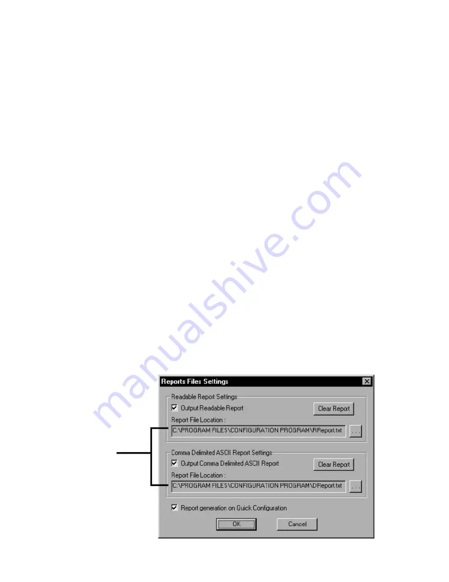
b. Select the type of report desired or both. See

Fig. 13.
Both files generated are ASCII files readable by
any text reader. A readable report is formatted in
ASCII with spaces and tabs to make it readable
when opened in programs such as Notepad.
Comma delimited formatting is useful when you
want to import the text into spreadsheet or database
programs. Clear the contents of a report by click-
ing Clear Report. If you wish reports to be gener-
ated when you run Quick Configuration, the
Report generation box must be checked.
Click OK.

3. To View reports in ASCII format.

a. Select Report Settings from the File menu.
b. Locate the path to the desired report. You can close

this window and the Configuration Manager if
desired.

c. Using a text reader such as Notepad or a word pro-

cessor, open the file.

4. Example: To import reports into Microsoft Excel:

a. Select Report Settings from the File menu.
b. Check Tab Delimited.
c. Open Microsoft Excel.
d. Select Import From the File menu. The Text

Import wizard appears.

e. Import the DReport.txt file.
f. Click Comma and Tab in the Delimiters box.
g. Click Next and fill out the rest of the wizard

as desired. Each comma in the delimited file
will be transformed into a column in the Excel
spreadsheet.

Serial Settings

NOTE: This unit is factory set for Carrier CCN use. Do not
change the unit Serial Settings.

Power Management — 

Power management features

are preset for the Carrier CCN application and do not need to
be altered. See Fig. 14 to view power modes.

Passwords and Access

LEVELS OF ACCESS — There are two levels of access:
OEM and USER. Each level has access to different sets of
fields in the Configuration Manager. A User has the lowest lev-
el of access and is only able to change parameters in some of
the fields available to OEMs. OEMs have access to all func-
tions. See Table 4.

All transceivers are shipped with OEM access. It is up to the

administrator to assign user privileges from that point on.
PASSWORDS — Change the password as frequently as you
desire. A password consists of any combination of numbers or
letters up to 29 characters. Contact Carrier if a new password
file is needed. All units are shipped with “oem” as the pass-
word. It is recommended for security reasons to change your
password from the factory setting.

Depending on access level, you have User or OEM privi-

leges. The dialogs that appear and the options available vary by
privilege.
NOTE: All units are delivered with OEM privileges.

Location of
file

Location of
file

Fig. 13 — Report Settings

Summary of Contents for WIRELESS TRANSCEIVER 33CNOAANT1

Page 1: ...NGMOD kit contains the following wireless transceiver power supply RS 232 to RS 485 converter RS 232 cable and an antenna In order to communicate outdoors between structures an additional outdoor antenna part number 33CNOAANT1 is required for each wireless transceiver Frequency Hopping The Carrier wireless transceiv ers use Frequency Hopping Spread Spectrum FHSS technol ogy to ensure secure reliab...

Page 2: ...ed from the transceivers NOTE if antennas are connected and located too close together the two antenna fields will cancel each other out c Verify that cycling power to the modems shows the 3 flash blink as described in the Getting Status sec tion of this manual 10 After successfully establishing communications between the two transceivers locally locate the transceivers in their desired locations ...

Page 3: ...ional antennas provide essentially equal signal strength around the antenna b Omni directional antennas can receive a signal coming from virtually any direction in relation to the antenna as long as polarization is not a factor c Directional antennas provide greater signal strength in the direction that the antenna is oriented d Directional antennas are labeled with a vertical pole for proper orie...

Page 4: ...oot from any location in the building All CCN elements on the primary bus are accessible The wireless con nection allows the technician to utilize a laptop computer to perform all Service Tool functions from anywhere within the range of wireless communication If the transceiver is located on a rooftop it is possible to gain wireless access to the build ing from several miles away NOTE Wireless bus...

Page 5: ...ary buses Fig 3 Wireless Multiple Bus Extensions of Primary Bus NOTE Not recommended for use on sites with secondary buses Fig 4 Wireless Workstation NOTE Not recommended for use on sites with secondary buses Fig 5 Wireless Bus Extension of Primary Bus ...

Page 6: ...figuration on the General tab click it on the toolbar or select it from the Commands menu The Quick Configuration wizard appears with the Operating Mode window displayed 2 Select the desired Operating Mode 3 Select Broadcast Host for a network configuration of 2 or more transceivers on a Broadcast network When con figuring slave modems configure a remote to talk to all remotes on the network If ho...

Page 7: ...ck OK The Main Window appears A Tip of The Day window also appears A new tip of the day will appear each time you open the configuration program You can turn this off by unchecking the box Click OK to dismiss the window Getting Status Status lights on the Status bar indicate the status of the control lines on the RS 232 link between the PC and the transceiver being configured See Fig 9 and Table 3...

Page 8: ... are not sure you really want NOTE When you exit the configuration program these changes will not remain in effect You must click Store for them to become permanent STORE APPLIED SETTINGS Stores all Applied chang es into the transceiver s EEPROM These settings will remain in effect upon exiting the program Stored changes are over written when new stored entries are made or when you load the defaul...

Page 9: ...m the File menu b Locate the path to the desired report You can close this window and the Configuration Manager if desired c Using a text reader such as Notepad or a word pro cessor open the file 4 Example To import reports into Microsoft Excel a Select Report Settings from the File menu b Check Tab Delimited c Open Microsoft Excel d Select Import From the File menu The Text Import wizard appears ...

Page 10: ...n the transceiver is compared to the Hop Table with the same number in the Configuration Manager database The Advanced Settings tab provides the selected Hop Table number and whether the Hop Table has passed validation and the first and last indices used for the Hop Table Index values are set to meet the requirements of the country in which the transceiver is deployed for a minimum number of hop f...

Page 11: ...nsceiver no 2 NOTE You will only see received data if the destination transceiver is con nected to a PC with Configuration loaded and open or if the destination PC s transceiver has a loopback connector What You Need Two transceivers A and B configured as a host to remote The Source Unit ID of unit A equals the Desti nation Unit ID of unit B and vice versa In addition both units must have matching...

Page 12: ...back Test tab 3 In Test String enter some text 4 Enter the desired criteria in other fields in this group The default values are recommended for this type of testing The minimum for Repeat Every field is 100 msec 5 Click Start Test the Placement of a Unit 1 Click the Loopback Test tab See Fig 19 2 Click Test 3 Click Instantaneous RSSI 4 Enter some text in the Test String 5 Enter the desired criter...

Page 13: ...13 Fig 18 RX Configuration Window Fig 19 Loopback Test Window ...

Page 14: ... most if not all cases A directional antenna can extend your range by concen trating the radiated energy from the antenna in a certain direc tion Also a directional antenna will only receive signals that are in its specific angle reception RF interference outside the antennas area will not be visible by the antenna and in this way can increase the transceivers receive capability Q The range specif...

Page 15: ...cause of wireless interference A Yes although Carrier wireless modems are designed to avoid communication interruption it is possible for the user to see duplicate alarms on a ComfortWORKS or Comfort VIEW display due to wireless interference Q Are there limits to the application of wireless CCN communications A Yes As with any wireless communication the transceiver can be interfered with by a phys...

Page 16: ...ontinue or change at any time specifications or designs without notice and without incurring obligations PC 111 Catalog No 533 378 Printed in U S A Form 33CN 1SI Pg 16 4 01 Replaces New Copyright 2001 Carrier Corporation Book 1 4 Tab 11a 13a ...

Reviews: