background image

7

k. Repeat as necessary for more transceivers.
l.

Check Report Generation.

m. Click Close.
n. Click Cancel.
o. Select Exit from the file menu.

6. View the report.

a. Open Windows Explorer.
b. Once in Windows Explorer, Open the following

file:  C:\Program Files\Configuration Manager\
RReport.txt.

7. Test Operation.

Connect transceiver no. 1 to the host PC. Connect trans-
ceiver no. 2 to the loopback connector. Ensure all
transceivers have power and have antennas properly con-
nected. Run the loopback test in the Unit Testing section
of this manual. Repeat with the host and each remote unit.

ADVANCED CONFIGURATION

The Configuration Manager is used to configure all trans-

ceivers being used in the network. The procedures in this sec-
tion describe how to configure the transceiver to meet your
specific needs. This section should be used in conjunction with
the Typical Set Ups (Quick Start) section. See Fig. 8.

To open your Configuration Management application:

1. From the Start menu in Windows, select Programs and

then Configuration Manager.
A splash screen appears with a Login dialog on top re-
questing username and password.

2. Enter the username: “oem”
3. Enter the password: “oem”

NOTE: “oem” is lower case.

4. Click OK. The Main Window appears. A Tip of The Day

window also appears. A new tip of the day will appear
each time you open the configuration program. You can
turn this off by unchecking the box. Click OK to dismiss
the window.

Getting Status — 

Status lights on the Status bar indicate

the status of the control lines on the RS-232 link between the PC
and the transceiver being configured. See Fig. 9 and Table 3.

In addition to the status lights in the Configuration Manager,

the LED’s on the stand-alone transceiver also display status.
See Fig. 10.

Exiting the Program — 

In order to exit the Configura-

tion Manager, refer to the following.

Select Exit from the File menu.

NOTE: It is important to note that any changes in any tab not
stored in EEPROM will be lost.

Table 3 — Status Definitions

ABBREVIATION

NAME

DEFINITION

RI

Ring Indicator

A signal is coming 
into the host unit 
from the transceiver 
at the remote unit.

DCD

 Data Carrier Detect

A connection has 
been established 
with another unit. 
This lets the PC 
know that communi-
cation between two 
units can take place.

DTR

Data Terminal 

Ready

Indicates that the 
unit is in Command 
Mode. This mode is 
utilized by the net-
work software.

RTS

Ready To Send

This is a hardware 
flow control indicator

CTS

Clear To Send

A hardware control 
indicator

 DSR

Data Set Ready

Reserved for future 
use

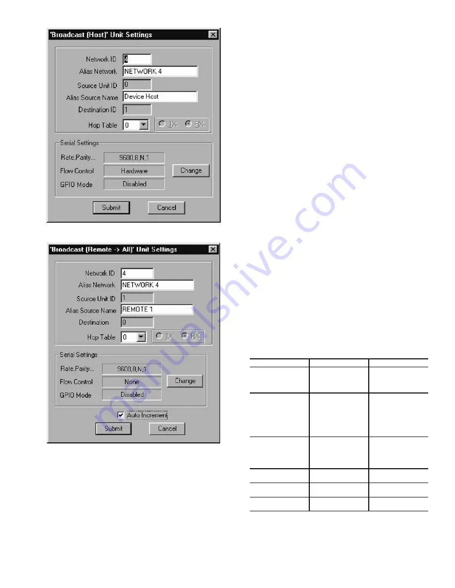
Fig. 6 — Host to Broadcast Set Up

Fig. 7 — Transceiver 2 Configuration

Summary of Contents for WIRELESS TRANSCEIVER 33CNOAANT1

Page 1: ...NGMOD kit contains the following wireless transceiver power supply RS 232 to RS 485 converter RS 232 cable and an antenna In order to communicate outdoors between structures an additional outdoor antenna part number 33CNOAANT1 is required for each wireless transceiver Frequency Hopping The Carrier wireless transceiv ers use Frequency Hopping Spread Spectrum FHSS technol ogy to ensure secure reliab...

Page 2: ...ed from the transceivers NOTE if antennas are connected and located too close together the two antenna fields will cancel each other out c Verify that cycling power to the modems shows the 3 flash blink as described in the Getting Status sec tion of this manual 10 After successfully establishing communications between the two transceivers locally locate the transceivers in their desired locations ...

Page 3: ...ional antennas provide essentially equal signal strength around the antenna b Omni directional antennas can receive a signal coming from virtually any direction in relation to the antenna as long as polarization is not a factor c Directional antennas provide greater signal strength in the direction that the antenna is oriented d Directional antennas are labeled with a vertical pole for proper orie...

Page 4: ...oot from any location in the building All CCN elements on the primary bus are accessible The wireless con nection allows the technician to utilize a laptop computer to perform all Service Tool functions from anywhere within the range of wireless communication If the transceiver is located on a rooftop it is possible to gain wireless access to the build ing from several miles away NOTE Wireless bus...

Page 5: ...ary buses Fig 3 Wireless Multiple Bus Extensions of Primary Bus NOTE Not recommended for use on sites with secondary buses Fig 4 Wireless Workstation NOTE Not recommended for use on sites with secondary buses Fig 5 Wireless Bus Extension of Primary Bus ...

Page 6: ...figuration on the General tab click it on the toolbar or select it from the Commands menu The Quick Configuration wizard appears with the Operating Mode window displayed 2 Select the desired Operating Mode 3 Select Broadcast Host for a network configuration of 2 or more transceivers on a Broadcast network When con figuring slave modems configure a remote to talk to all remotes on the network If ho...

Page 7: ...ck OK The Main Window appears A Tip of The Day window also appears A new tip of the day will appear each time you open the configuration program You can turn this off by unchecking the box Click OK to dismiss the window Getting Status Status lights on the Status bar indicate the status of the control lines on the RS 232 link between the PC and the transceiver being configured See Fig 9 and Table 3...

Page 8: ... are not sure you really want NOTE When you exit the configuration program these changes will not remain in effect You must click Store for them to become permanent STORE APPLIED SETTINGS Stores all Applied chang es into the transceiver s EEPROM These settings will remain in effect upon exiting the program Stored changes are over written when new stored entries are made or when you load the defaul...

Page 9: ...m the File menu b Locate the path to the desired report You can close this window and the Configuration Manager if desired c Using a text reader such as Notepad or a word pro cessor open the file 4 Example To import reports into Microsoft Excel a Select Report Settings from the File menu b Check Tab Delimited c Open Microsoft Excel d Select Import From the File menu The Text Import wizard appears ...

Page 10: ...n the transceiver is compared to the Hop Table with the same number in the Configuration Manager database The Advanced Settings tab provides the selected Hop Table number and whether the Hop Table has passed validation and the first and last indices used for the Hop Table Index values are set to meet the requirements of the country in which the transceiver is deployed for a minimum number of hop f...

Page 11: ...nsceiver no 2 NOTE You will only see received data if the destination transceiver is con nected to a PC with Configuration loaded and open or if the destination PC s transceiver has a loopback connector What You Need Two transceivers A and B configured as a host to remote The Source Unit ID of unit A equals the Desti nation Unit ID of unit B and vice versa In addition both units must have matching...

Page 12: ...back Test tab 3 In Test String enter some text 4 Enter the desired criteria in other fields in this group The default values are recommended for this type of testing The minimum for Repeat Every field is 100 msec 5 Click Start Test the Placement of a Unit 1 Click the Loopback Test tab See Fig 19 2 Click Test 3 Click Instantaneous RSSI 4 Enter some text in the Test String 5 Enter the desired criter...

Page 13: ...13 Fig 18 RX Configuration Window Fig 19 Loopback Test Window ...

Page 14: ... most if not all cases A directional antenna can extend your range by concen trating the radiated energy from the antenna in a certain direc tion Also a directional antenna will only receive signals that are in its specific angle reception RF interference outside the antennas area will not be visible by the antenna and in this way can increase the transceivers receive capability Q The range specif...

Page 15: ...cause of wireless interference A Yes although Carrier wireless modems are designed to avoid communication interruption it is possible for the user to see duplicate alarms on a ComfortWORKS or Comfort VIEW display due to wireless interference Q Are there limits to the application of wireless CCN communications A Yes As with any wireless communication the transceiver can be interfered with by a phys...

Page 16: ...ontinue or change at any time specifications or designs without notice and without incurring obligations PC 111 Catalog No 533 378 Printed in U S A Form 33CN 1SI Pg 16 4 01 Replaces New Copyright 2001 Carrier Corporation Book 1 4 Tab 11a 13a ...

Reviews: