background image

10

USER FUNCTIONS — To change the password as a user:

1. Select Change Password from the File menu. Change

password dialog appears. See Fig. 15.

2. Enter the desired criteria.

Enter user name and new password. Retype the new pass-
word in Confirm Password. 

3. Click OK. 

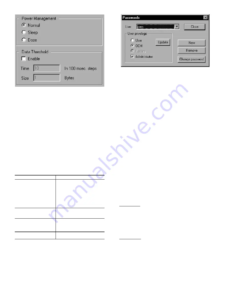
OEM FUNCTIONS — All units are delivered with default
OEM privileges. The system administrator must set units to
User access.

To access OEM privileges:

1. Select Change Password from the File menu. See Fig. 16.
2. Change password dialog appears.
3. Select the desired User name from the list.
4. Change user permissions as desired.

Table 4 — Privilege Options

Using Hop Tables — 

A Hop Table is a listing of fre-

quencies in a given spectrum that are used for communication.
Data is sent to each frequency in the table in a hopping pattern.
Hop Tables provide improved security and the ability to avoid
localized noise sources. There are 101 possible Hop Tables in
your transceiver (this number may vary for international trans-
ceiver models). These are subdivided into five completely in-
dependent, non-overlapping Hop Table sets, each with no more
than three consecutive frequencies. Each individual network
can only utilize one Hop Table.

ENTERING HOP TABLE NUMBERS — Hop  Table  num-
bers can only be entered or changed by using the Quick Con-
figuration wizard.

Enter the desired identification numbers. See Assigning IDs

section for acceptable parameters. Select a Hop Table (0 to
100). The Hop Table selected must be the same for all trans-
ceivers in a Point-To-Point or a Network. This number speci-
fies a table of predefined frequencies, which the transceiver
will use for transmitting and receiving. If multiple separate net-
works exist in the same area, each network should have a
unique Hop Table number to avoid RF collisions. Depending
on which network is selected in the previous screen, certain ID
fields may be grayed and inaccessible.

If multiple isolated wireless networks are installed in the

same area, it is recommended that hop tables 1-5 be used
sequentually.
VALIDATING THE HOP TABLE — This  command  veri-
fies the integrity of the Hop Table stored within the transceiver.
The Hop Table in the transceiver is compared to the Hop Table
with the same number in the Configuration Manager database.
The Advanced Settings tab provides the selected Hop Table
number and whether the Hop Table has passed validation and
the first and last indices used for the Hop Table. Index values
are set to meet the requirements of the country in which the
transceiver is deployed for a minimum number of hop frequen-
cies. These values can not be changed to avoid violating coun-
try regulations. To validate the Hop Table, from the Commands
menu, select Validate Hop Table.
SPECIFYING HOPPING PARAMETERS — You  can  cus-
tomize Hop Table parameters by setting some features avail-
able from the Advanced Settings tab. 
Max No Data — (Adjustment of these settings is not
recommended.)

Max No Data is the number of hop cycles that must pass

during which no data was received and no data was available
for transmission before a session can be declared down. It is
used as the trigger to end a session. After a certain number of
Frames No Data between both units, the master will terminate
the current session/link.
Max Bad Hop — (Adjustment of these settings is not
recommended.)

Max Bad Hop is the number of data frames with errors re-

ceived before a link is considered bad. This is the trigger to
stop the current link and wait for a random standoff period
(approx. 0.5 to 3 seconds). This is due to the assumption that
after 4 consecutive bad hops (system default but can be
changed), the link has been lost — either due to interference or
lost synchronization. By waiting a small amount of time before
attempting to reestablish the link, the obstruction (i.e., noise
source) may have moved somewhere else.

 PRIVILEGE

OPTIONS

User privileges

Assign privileges as OEM or User. 
They can also be assigned Admin-
istrator privilege which provides the 
ability to change user privileges. If 
you are assigned as a User, you 
can not add other users or change 
the passwords of other users. Click 
update for these changes to take 
effect.

New

Add a new user by typing in their 
name and password. You must 
retype the password to confirm it.

Change password

Change the password of an exist-
ing user by typing in their name 
and password. You must retype the 
password to confirm it.

 Remove users

Removes the currently selected 
user.

Fig. 14 — Power Management Window

Fig. 15 — Change Password Window

Summary of Contents for WIRELESS TRANSCEIVER 33CNOAANT1

Page 1: ...NGMOD kit contains the following wireless transceiver power supply RS 232 to RS 485 converter RS 232 cable and an antenna In order to communicate outdoors between structures an additional outdoor antenna part number 33CNOAANT1 is required for each wireless transceiver Frequency Hopping The Carrier wireless transceiv ers use Frequency Hopping Spread Spectrum FHSS technol ogy to ensure secure reliab...

Page 2: ...ed from the transceivers NOTE if antennas are connected and located too close together the two antenna fields will cancel each other out c Verify that cycling power to the modems shows the 3 flash blink as described in the Getting Status sec tion of this manual 10 After successfully establishing communications between the two transceivers locally locate the transceivers in their desired locations ...

Page 3: ...ional antennas provide essentially equal signal strength around the antenna b Omni directional antennas can receive a signal coming from virtually any direction in relation to the antenna as long as polarization is not a factor c Directional antennas provide greater signal strength in the direction that the antenna is oriented d Directional antennas are labeled with a vertical pole for proper orie...

Page 4: ...oot from any location in the building All CCN elements on the primary bus are accessible The wireless con nection allows the technician to utilize a laptop computer to perform all Service Tool functions from anywhere within the range of wireless communication If the transceiver is located on a rooftop it is possible to gain wireless access to the build ing from several miles away NOTE Wireless bus...

Page 5: ...ary buses Fig 3 Wireless Multiple Bus Extensions of Primary Bus NOTE Not recommended for use on sites with secondary buses Fig 4 Wireless Workstation NOTE Not recommended for use on sites with secondary buses Fig 5 Wireless Bus Extension of Primary Bus ...

Page 6: ...figuration on the General tab click it on the toolbar or select it from the Commands menu The Quick Configuration wizard appears with the Operating Mode window displayed 2 Select the desired Operating Mode 3 Select Broadcast Host for a network configuration of 2 or more transceivers on a Broadcast network When con figuring slave modems configure a remote to talk to all remotes on the network If ho...

Page 7: ...ck OK The Main Window appears A Tip of The Day window also appears A new tip of the day will appear each time you open the configuration program You can turn this off by unchecking the box Click OK to dismiss the window Getting Status Status lights on the Status bar indicate the status of the control lines on the RS 232 link between the PC and the transceiver being configured See Fig 9 and Table 3...

Page 8: ... are not sure you really want NOTE When you exit the configuration program these changes will not remain in effect You must click Store for them to become permanent STORE APPLIED SETTINGS Stores all Applied chang es into the transceiver s EEPROM These settings will remain in effect upon exiting the program Stored changes are over written when new stored entries are made or when you load the defaul...

Page 9: ...m the File menu b Locate the path to the desired report You can close this window and the Configuration Manager if desired c Using a text reader such as Notepad or a word pro cessor open the file 4 Example To import reports into Microsoft Excel a Select Report Settings from the File menu b Check Tab Delimited c Open Microsoft Excel d Select Import From the File menu The Text Import wizard appears ...

Page 10: ...n the transceiver is compared to the Hop Table with the same number in the Configuration Manager database The Advanced Settings tab provides the selected Hop Table number and whether the Hop Table has passed validation and the first and last indices used for the Hop Table Index values are set to meet the requirements of the country in which the transceiver is deployed for a minimum number of hop f...

Page 11: ...nsceiver no 2 NOTE You will only see received data if the destination transceiver is con nected to a PC with Configuration loaded and open or if the destination PC s transceiver has a loopback connector What You Need Two transceivers A and B configured as a host to remote The Source Unit ID of unit A equals the Desti nation Unit ID of unit B and vice versa In addition both units must have matching...

Page 12: ...back Test tab 3 In Test String enter some text 4 Enter the desired criteria in other fields in this group The default values are recommended for this type of testing The minimum for Repeat Every field is 100 msec 5 Click Start Test the Placement of a Unit 1 Click the Loopback Test tab See Fig 19 2 Click Test 3 Click Instantaneous RSSI 4 Enter some text in the Test String 5 Enter the desired criter...

Page 13: ...13 Fig 18 RX Configuration Window Fig 19 Loopback Test Window ...

Page 14: ... most if not all cases A directional antenna can extend your range by concen trating the radiated energy from the antenna in a certain direc tion Also a directional antenna will only receive signals that are in its specific angle reception RF interference outside the antennas area will not be visible by the antenna and in this way can increase the transceivers receive capability Q The range specif...

Page 15: ...cause of wireless interference A Yes although Carrier wireless modems are designed to avoid communication interruption it is possible for the user to see duplicate alarms on a ComfortWORKS or Comfort VIEW display due to wireless interference Q Are there limits to the application of wireless CCN communications A Yes As with any wireless communication the transceiver can be interfered with by a phys...

Page 16: ...ontinue or change at any time specifications or designs without notice and without incurring obligations PC 111 Catalog No 533 378 Printed in U S A Form 33CN 1SI Pg 16 4 01 Replaces New Copyright 2001 Carrier Corporation Book 1 4 Tab 11a 13a ...

Reviews: