


54
CHECKOUT
Inspect all wiring connections at the economizer module’s termi-
nals, and verify compliance with the installation wiring diagrams.
For checkout, review the Status of each configured parameter and
perform the Checkout tests.
NOTE: For information about menu navigation and use of the
keypad see Interface Overview on page 45.
Power Up
After the W7220 module is mounted and wired, apply power.
Initial Menu Display
On initial start up, Honeywell displays on the first line and
economizer W7220 on the second line. After a brief pause, the
revision of the software appears on the first line and the second
line will be blank.
Power Loss (Outage or Brownout)
All set points and advanced settings are restored after any pow-
er loss or interruption.
NOTE: All settings are stored in non-volatile flash memory.
Status
Use the Status menu (see Table 20) to check the parameter val-
ues for the various devices and sensors configured.
NOTE: For information about menu navigation and use of the
keypad, see Interface Overview on page 45.
Checkout Tests
Use the Checkout menu (see page 50) to test the damper opera-
tion and any configured outputs. Only items that are config-
ured are shown in the Checkout menu.
NOTE: For information about menu navigation and use of the
keypad, see Interface Overview on page 45.
To perform a Checkout test:
1. Scroll to the desired test in the Checkout menu using the
▲
and
▼
buttons.
2. Press the
(Enter) button to select the item. RUN?
appears.
3. Press the
(Enter) button to start the test. The unit
pauses and then displays IN PROGRESS. When the test is
complete, DONE appears.
4. When all desired parameters have been tested, press the
(Menu Up) button to end the test.
The Checkout tests can all be performed at the time of installa-
tion or at any time during the operation of the system as a test
that the system is operable.
TROUBLESHOOTING
Alarms
The economizer module provides alarm messages that display
on the 2-line LCD.
NOTE: Upon power up, the module waits 60 minutes before
checking for alarms. This allows time for all the configured devic-
es (e.g. sensors, actuator) to become operational. The exception is
the SAT sensor which will alarm immediately.
If one or more alarms are present and there has been no keypad
activity for at least 5 minutes, the Alarms menu displays and
cycles through the active alarms.
You can also navigate to the Alarms menu at any time.
Clearing Alarms
Once the alarm has been identified and the cause has been re-
moved (e.g. replaced faulty sensor) the alarm can be cleared
from the display.
To clear an alarm, perform the following:
1. Navigate to the desired alarm.
2. Press the
(Enter) button. ERASE? displays.
3. Press the
(Enter) button. ALARM ERASED displays.
4. Press the
(Menu up/Exit) button to complete the
action and return to the previous menu.
If the alarm still exists after clearing it, it is redisplayed within
5 seconds.
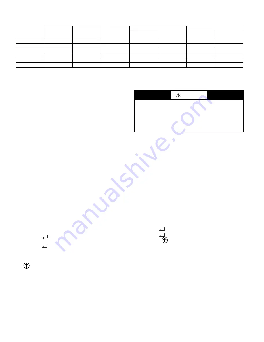
Table 26 — Single Enthalpy and Dual Enthalpy High Limit Curves
ENTHALPY
CURVE
TEMP. DRY
BULB (F)
TEMP.
DEWPOINT (F)
ENTHALPY
(btu/lb/da)
POINT P1
POINT P2
TEMP. (F)
HUMIDITY
(%RH)
TEMP. (F)
HUMIDITY
(%RH)
ES1
8
0
60
2
8
.0
8
0
36.
8
66.3
8
0.1
ES2
75
57
26.0
75
39.6
63.3
8
0.0
ES3
70
54
24.0
70
42.3
59.7
8
1.4
ES4
65
51
22.0
65
44.
8
55.7
8
4.2
ES5
60
4
8
20.0
60
46.9
51.3
88
.5
HL
8
6
66
32.4
8
6
3
8
.9
72.4
8
0.3
CAUTION
EQUIPMENT DAMAGE HAZARD
Failure to follow this caution may result in equipment dam-
age.
Be sure to allow enough time for compressor start-up and
shutdown between checkout tests so that you do not short-
cycle the compressors.
Summary of Contents for WeatherMaker 50KCQ A04 Series
Page 34: ...34 Fig 53 RTU Open Overlay for Economizer Wiring ...
Page 35: ...35 Fig 54 VFD Overlay for W2770 Controller Wiring ...
Page 70: ...70 Fig C 50KCQ A04 A05 A06 Control Wiring Diagram 575 3 60 APPENDIX D WIRING DIAGRAMS ...
Page 71: ...71 Fig D 50KCQ A04 A05 A06 Power Wiring Diagram 208 230 1 60 APPENDIX D WIRING DIAGRAMS ...
Page 72: ...72 Fig E 50KCQ A04 A05 A06 Power Wiring Diagram 208 230 3 60 APPENDIX D WIRING DIAGRAMS ...
Page 73: ...73 Fig F 50KCQ A04 A05 A06 Power Wiring Diagram 460 3 60 APPENDIX D WIRING DIAGRAMS ...
Page 74: ...74 Fig G 50KCQ A04 A05 A06 Power Wiring Diagram 575 3 60 APPENDIX D WIRING DIAGRAMS ...
Page 75: ...75 Fig H 50KCQ Premier Link Control Diagram APPENDIX D WIRING DIAGRAMS ...
Page 76: ...76 Fig I 50KCQ RTU Open Control Diagram APPENDIX D WIRING DIAGRAMS ...


