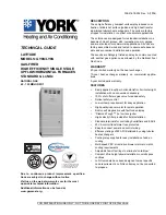
background image

Fig.

19—Wiring

Diagram

for

Two-Stage

Non-Condensing

Furnaces

A02159

GV

HI

M

G

RN/

Y

E

L

C

NO

T

E

 #3

BR

N

BL

U

BR

N

G

R

N

/YEL

RE

D

RE

D

RE

D

NO

T

E

 #

11

FR

S

1

DS

S

BVS

S

LS

1

(W

HE

N

 US

E

D

)

FR

S

2

NO

T

E

 #1

2

OR

N

YEL

HS

I

L1

NO

T

E

 #

2

GN

D

NE

UT

R

A

L

FU

2

FU

SE

 O

R

 C

IR

C

U

IT

B

R

EA

K

ER &

 DI

SC

O

N

N

EC

T

SWI

TC

H

 (

W

HE

N

 R

EQ'

D

)

BL

K

IL

K

PL

5

JB

1

2

SEC

-1

LE

D

SEC

-2

FUSE

 3-A

MP

PL

T

AC

R

D

J

0.5 A

MP

@ 24 VA

C

HUM

TEST/

TW

IN

ON

OF

F

3
2
1

DLY 
OFF

LHT

W/

W

1

D

HUM

G

24

V

om

C

W

2

Y/

Y2

R

Y1

TR

A

N

L1

PR-1

EAC

-1

CA

P

OL

SPARE

 - 1

BLW

R

BHT/CLR

BHI/LO

R

COOL

LO-HE

AT

HI-HE

AT

ST

AR

T

GR

N

/Y

E

L

BLWM

NEUT

RAL -

 L2

EAC

-2

RE

D

BLU

OR

N

YEL

BLK

LO

ME

D

 L

O

MED

HI

M

E

D HI

RE

D

BL

U

WH

T

WH

T

BR

N

BR

N

BLK

WH

T

BLK

WH

T

IH

I/L

O

R

HS

IR

ID

R

LO

HI

HSI

GR

Y

CO

NNE

C

T

IO

N

 DI

A

G

R

A

M

BLK

1

HS

I

2

ID

M

1

2

3

HI

CO

M

LO

    S

C

H

E

MA

T

IC DI

A

G

R

A

M

(N

AT

U

R

A

L

 G

A

S & PR

O

PAN

E

)

ID

R

    TO

 1

1

5

VAC

 FI

ELD-

DI

SCO

NNECT 

SW

IT

CH

EQ

U

IP

M

EN

T

 GR

O

U

N

D

1

2

3

HS

IR

IH

I/L

O

R

PL2

L2

L2

CA

P

OL

ST

AR

T

BL

W

M

CO

M

LO

ME

D

 L

O

ME

D

HI

M

E

D HI

LO

 H

EAT

SPA

R

E

-2

C

OOL

IN

G

SP

AR

E

-1

BH

I/LO

R

BH

T

/C

L

R

BL

W

R

EAC

-2

EAC

-1

TR

A

N

L2

L2

11

5V

AC

2

4

VAC

SEC

 2

SE

C

 1

PR

1

FU

1

NO

T

E

 #6

FR

S

1

DS

S

BV

SS

FR

S

2

(W

H

E

N US

E

D

)

PL1

-8

GV

R

-2

HU

M

R

AC

R

P

L1-

12

HP

S

R

GV

LPS

NO

T

E

 #

12

LG

P

S

(W

HE

N U

S

E

D

)

HP

S

HI

PL1

-2

P

L1-

4

P

L1-

3

PL1

-1

0

PL1

-5

W/

W1

CP

U

GV

R

-1

TE

S

T

/T

WI

N

DHU

M

W2

Y/

Y2

G

Y1

C

OM

  2

4V

NO

T

E

 #

3

C

M

P

L1-

1

LP

S

(W

H

E

N USE

D

)

LG

P

S

WH

T

FS

E

PL1

-9

PL1

-1

1

P

L1-

7

LEG

E

ND

AC

R

A

IR

 C

O

NDI

TI

O

NI

NG R

E

LA

Y,

 SP

ST 

(N.O.

)

AC

RD

J

A

IR

 C

O

NDI

TI

O

NI

NG R

E

LA

Y

 D

ISAB

LE

 J

U

MP

ER

B

H

I/

LO

R

B

LO

WER M

O

TO

R

 SP

EED 

C

H

ANGE

 REL

A

Y,

 S

P

D

T

B

H

T/

C

LR

B

LO

WER M

O

TO

R

 SP

EED 

C

H

ANGE

 REL

A

Y,

 S

P

D

T

B

LWR

B

LOWER M

O

TO

R

 R

E

LA

Y,

 SP

ST

-(

N.O.)

B

LWM

B

LOWER M

O

TO

R

P

E

R

M

AN

ENT-

SP

LI

T-

C

A

PA

C

ITOR

BV

SS

BLO

C

K

E

D

 V

E

N

T S

H

U

TO

FF

 S

W

IT

CH

, M

A

N

U

A

L-R

E

SE

T,

 S

P

ST

 -(

N

.C.

)

C

A

P

C

AP

AC

IT

OR

C

P

U

M

IC

R

O

P

R

OC

ESSOR AND C

IR

C

UI

TRY

DH

U

M

DH

U

M

 CO

N

N

E

CT

IO

D

SS

D

RAF

T S

A

FE

 GUA

R

D S

W

IT

C

H

AUT

O-

RESET

SP

ST

 -

(N.C

.)

EA

C

-1

E

LEC

TR

ON

IC

 A

IR

 C

LEA

N

E

R

 C

O

N

N

EC

TION

 (

115 

V

A

C

 1

.0 

A

M

P

 M

A

X

.)

EAC

-2

EL

EC

TR

ONIC

 AI

R C

LEANER C

O

N

N

EC

TION

 (C

O

M

MON)

FR

S 1

, 2

FL

A

ME R

O

LL

OU

SW

. -

M

ANUAL

 RESET

SP

ST-

(N

.C

.)

FS

E

FL

A

M

E

-P

ROV

IN

G

 EL

EC

TR

OD

E

FU

1

FUS

E, 

3

 AMP

, AU

TOMOTI

V

E B

LADE T

Y

P

E

FA

C

TOR

Y

 IN

ST

AL

LE

D

FU

2


FU

SE

 OR 

C

IRC

U

IT 

B

R

EAK

E

R C

U

RRENT

 INT

E

RRUP

T D

E

V

IC

E


(F

IE

LD

 S

U

P

P

LI

ED AND I

N

ST

AL

LE

D)

GND

E

QU

IP

M

ENT GROU

ND

GV

GAS

 V

A

LV

E

-R

E

DUN

DANT 

GV

1

, 2

G

AS

 V

A

LV

E

 REL

A

Y,

 DP

ST-

(N

.O

.)

H

P

S

H

IG

H

-H

E

A

T P

R

ESSU

RE 

SW

IT

C

H

, SP

ST (N.O.

)

H

P

SR

H

IGH

-H

EA

P

R

ESSU

RE S

W

IT

C

H

 REL

A

Y,

 SP

ST (

N

.C

.)

H

SI

H

OT S

U

RF

AC

E IGNI

TER (

1

1

5

V

A

C

)

H

SIR

H

O

T S

U

RF

AC

E IGNI

TER REL

A

Y,

 SP

ST (

N

.O

.)

H

U

M

2

4

V

AC

 H

U

MI

DI

FI

ER C

O

NNEC

TI

ON 

(0

.5

 AMP

. MAX.

)

ID

M

INDU

C

ED DRAF

T MOTOR, SH

ADED-

P

O

LE

ID

R

INDU

C

E

DRAF

MOTOR REL

A

Y,

 SP

ST-

(N.

O

.)

IH

I/

LO

R

INDU

C

ER M

O

TOR S

P

EED

 C

H

ANGE 

REL

A

Y, SP

DT

IL

K

B

LO

WER 

AC

C

E

SS P

A

N

E

L INTERL

OC

K

 S

W

ITC

H

, SP

ST-

(N

.O.)

JB

JU

N

C

TI

O

N

 B

O

X

LE

D

LI

G

H

T-

E

MI

TTING

 D

IODE F

O

ST

A

TU

S C

O

DES 

AMB

ER

LG

P

S

LO

W GAS 

P

R

ES

SURE SWI

TC

H

SP

ST-

(N.O.

)

LP

S

LOW-

H

E

A

P

R

ESS

U

RE SWITC

H

SP

ST (

N

.O.)

LS

 1

, 2

LIMI

T S

W

IT

C

H

, AU

TO-

R

ESET

, SP

ST

 (

N

.C

.)

OL

AU

TO-

R

ESET INTERNA

L M

OTOR OV

ERL

OAD

 TEM

P

E

R

A

TU

RE SWI

TC

H

 (

N

.C

.)

P

C

B

P

RIN

TED

 C

IRC

U

IT 

B

O

ARD

 C

O

NTROL

PL1

12

-C

IR

C

U

IT

 PC

B CO

N

N

E

C

TO

R

P

L2

3

-C

IR

C

U

IT P

C

B H

SI 

& ID

M

 C

O

N

N

EC

TOR

P

L3

6

-C

IR

C

U

IT IC

M M

O

TO

R

 C

O

NN

EC

TOR 

(N

OT SH

OWN)

P

L4

3

-C

IR

C

U

IT ID

M

 C

O

N

N

E

C

TOR


P

L5

2

-C

IR

C

U

IT H

SI 

C

O

N

N

E

C

TOR

PL

T

3

-C

IR

C

U

IT

 F

A

CT

O

R

Y

 T

E

ST

 CO

N

N

E

CT

O

R

TR

A

N

TR

A

N

SF

O

R

M

E

R

, 115V

A

C

/24V

A

C

TES

T/

TWI

N

C

O

M

P

O

N

ENT TEST 

& TW

IN

NING 

TERM

INAL

JU

N

C

TI

O

N

UNM

ARK

ED T

E

RMI

N

AL

P

C

B

 C

O

N

TROL

 T

E

RM

IN

AL

FA

C

TO

R

Y

 P

O

W

E

R

 W

IR

IN

G

 (

115V

A

C

)

FA

CT

O

R

Y CO

N

TR

O

L W

IR

IN

G

 (2

4

V

A

C

)

FI

EL

D C

O

NTROL

 WI

RING (

1

1

5

V

A

C

)

FI

EL

D C

O

NTROL

 WI

RING (

2

4

V

AC

)

C

O

NDU

C

TOR ON 

C

O

N

TROL

 P

C

B

FI

EL

D W

IR

ING 

SC

REW

 TERMI

N

A

L

FI

E

LD

 E

A

R

TH G

R

O

U

N

D

EQU

IP

M

ENT

 GROU

ND

FI

E

LD

 S

P

LI

C

E

P

LU

G

 REC

EP

TA

C

LE

PC

B


PL1

-6

L1

NO

T

E

 #10

L2

PL

4

PL

5

WH

T

G

R

N

/YEL

WH

T

RE

D

BL

K

ID

M

CO

M

LO

PL4

1

3

2

H I

WH

T

RE

D

BLK

PL

2

ID

M

NO

TE #8

1 AM

@ 115

 VA

C

STATUS C

O

D

E

FU1

NO

TE #6

PL

1

1

SELE

C

T

 C

H

AR

T

SW

LO

-H

T

ON

L

Y

BL

O

W

E

R

O

FF-

D

E

L

A

Y

ON

OF

F

1

ON

L

Y

HE

A

T

LO

H

EAT

NO

R

M

2

3

90

SEC

.

ON

OFF

1

2

3

120

SEC

.

ON

OFF

2

3

150

SEC

.

ON

OF

F

2

3

180

SE

C

.

HP

S

FA

C

T

O

R

Y

 S

E

TT

IN

G

S

BLW

HI

 HE

A

T

NO

T

E

 #

11

NO

T

E

 #

5

*

*

*

SPA

RE

-2

FS

E

RE

D

ACRDJ

327561-

101 R

E

V

. E

1

.

If

 a

n

y o

f th

o

ri

g

in

al

 e

q

ui

pment

 wi

re

 i

s

 r

e

p

lace

d us

e w

ir

e

 r

a

te

fo

r 1

0

5

C.

2

.

U

s

e

 onl

y

 coppe

r w

ire

 bet

w

e

e

n

 t

h

e

 di

s

c

onne

ct

 s

w

it

c

h

 and

 the

 f

urna

c

e

 j

unct

ion box

 (J

B

).

3.

T

h

is

 w

ir

e

 m

u

s

b

e

 c

o

nn

ec

te

to

 fu

rn

ace

 sh

e

e

t m

e

ta

l f

o

con

tr

o

l t

o

 pr

o

v

e

 f

lam

e.

4.

S

y

m

b

o

ls a

re

 ele

ct

rica

l r

e

p

re

sen

ta

ti

o

n

 o

n

ly.

5

.

Sol

id

 l

ine

s

 i

n

s

ide PC

B

 a

re

 pr

in

te

d ci

rc

ui

t boa

rd

 co

ndu

ctor

s a

n

d a

re not

 in

cl

ude

in

 the l

e

gend

.

6

.

R

e

p

lace

 onl

y

 wi

th a 3

 amp f

u

se

.

7.

B

lo

w

e

r m

o

to

r (B

LW

M

an

d

 in

d

u

c

e

r m

o

to

(I

D

M

) c

o

nt

ain

 in

ter

n

a

l au

to

-r

e

set

 t

h

er

m

a

l o

v

e

rl

o

ad 

s

w

it

ch

es

 (

O

L

).

8

.

N

e

u

tr

a

l con

nec

ti

o

n

s

 a

re

 int

e

rc

hang

eab

le

 w

it

h

in

 t

h

e

 N

E

U

T

R

A

L

 conn

ect

or

 b

lo

c

k

.

9

.

B

low

er mot

o

r spe

e

d

 s

e

le

c

ti

ons

 are

 f

o

r a

v

e

ra

g

e c

o

ndi

ti

o

n

s

s

e

e

 i

n

st

al

la

ti

o

n

 ins

truc

ti

ons

 for

 opt

im

um 

s

e

le

c

ti

on.

1

0

.

F

a

c

to

ry

 s

h

ip

p

e

d

 wit

h

 BL

UE 

wir

e

 (

M

ED

 L

O

) if

 O

RANG

E w

ir

e

 n

o

t p

re

s

e

n

t.

1

1

.

Fa

c

tor

y c

onne

c

ted w

h

e

n

 B

VSS (C

hi

mne

y

 A

d

a

p

ter

 K

it)

 i

s

 not i

n

s

tal

le

d.

1

2

.

Fa

c

tor

y c

onne

c

te

d whe

n

 LG

PS is

 not

 us

e

d

.

1

3

.

Ig

n

it

ion 

lo

cko

u

w

il

l occ

ur

 af

te

r f

our co

ns

ec

uti

v

e

 unsu

c

ces

sf

ul

 tri

a

ls

-f

o

r-

igni

ti

on.

  C

o

ntr

o

l w

il

a

u

to

-r

es

et

 a

ft

e

r

th

ree h

o

ur

s.

1

4

.

B

low

er-

on de

la

y

: gas

 hig

h

-h

ea

t 2

5

 se

co

nds,

 ga

s l

o

w-

he

at 4

5

 s

e

c

o

nd

s, c

ool

ing or

 he

a

t pump 2 s

e

c

o

nd

s.

1

5

.

B

low

er of

f-d

e

lay

: gas

 hea

ti

ng s

e

le

c

tions

 ar

e 9

0

, 1

2

0

, 150

1

8

0

 s

e

co

nds,

 c

ooli

n

g or hea

pum

p

 90

 sec

onds

 or


5

 se

co

nds wh

e

n

 D

H

U

M

 i

s

 act

ive

.

NOT

E

S

:

PRINTED CIRCIUT BOARD

PRINTED CIRCIUT BOARD

RE

D

LS

2

(W

HE

N

 US

E

D

)

LS

2

(W

HE

N U

S

E

D

)

LS

1

IL

K

L1

—24—

Summary of Contents for KGATW0601HSI

Page 1: ...ctrical Supply Connections 34 Start Up and Adjustment 34 Sequence of Operation 36 Fixed Capacity Furnaces 36 SAFETY CONSIDERATIONS Installing and servicing of heating equipment can be hazardous due to...

Page 2: ...should be at least as high upflow downflow or as long horizontal as the width of one furnace Supply air dampers when used should be installed in the branch ducts not in the common plenum Fire or smoke...

Page 3: ...furnace Example 2 8 MIN Common Return Air Plenum Return Air Plenum Return Air Plenum Twinned Furnace Common Supply Air Plenum Fig 2 Downflow Horizontal Ductwork Connections A02224 A A A A A A Common...

Page 4: ...r installed and uninstalled ungrounded furnaces 6 Before removing a new control from its container discharge your body s electrostatic charge to ground to protect the control from damage If the contro...

Page 5: ...imit switch cycling will occur 4 Remove bottom closure panels from both furnaces See Fig 4 a Lay furnaces on back or sides b Remove 2 screws from bottom front panel c Rotate front panel downward to re...

Page 6: ...e top of discharge opening and through both furnaces See Fig 6 Drill two 1 8 in holes approximately 1 in below return air flange from inside top of return air opening and through both furnaces See Fig...

Page 7: ...strips equal distance from top and bottom as shown in Fig 5 Trim off excess material 6 Determine which side of furnace will be used to route external extension harness Remove 7 8 in diameter accessor...

Page 8: ...onal support along the bottom of the rafter or joist Consult local or regional building codes for design and loading requirements For suspended installations See Fig 8b Not recommended for wood trusse...

Page 9: ...e d Remove bottom closure panel and set aside for possible use as roll out protection e Reinstall bottom front panel f Stand furnaces upright Fig 8b Suspended Installation for Horizontal Furnaces Back...

Page 10: ...in the horizontal position consideration must be made to the type of building construction Attic floors should be constructed to support normal live and dead loads of the furnaces and the person s se...

Page 11: ...r compartment and through both furnaces See Fig 7 10 Drive 1 factory supplied screw through each hole and tighten until furnaces are secure and foam strips have sealed gap between furnaces 11 Connect...

Page 12: ...e blower compartment d Install the lock nuts on the 90 conduit connectors e Install 2 kit supplied straps approximately 18 inches from each end of harness Single Stage Heat with Single Stage Gas Heat...

Page 13: ...econdary Harness includes the Auxiliary Door Switch and Auxiliary Limit Switch The harness is also tagged Secondary Furnace near the plug ends of the harness a Connect red wire labeled R Secondary to...

Page 14: ...s 7 Dress wires to ensure they do not contact sharp or moving parts nor interfere with blower operation removal of filters or operation of switches 8 Make all thermostat connections to LH furnace only...

Page 15: ...by side only 2 harness assemblies are required If the furnaces are installed back to back all 3 harness assemblies included in the kit must be used 1 Remove outer doors and blower access doors from bo...

Page 16: ...harness on R H furnace The Secondary Harness includes the Auxiliary Door Switch and Auxiliary Limit Switch The harness is also tagged Secondary Furnace near the plug ends of the harness a Connect red...

Page 17: ...nnect any connection other than supply and return air ducts Furnaces are recommended to be provided with a single shutoff valve However individual shutoff valves may be required by local codes or juri...

Page 18: ...C Y OUTDOOR UNIT NO 2 LEGEND NOTES Y G W R COM NOTE 3 NOTE 6 327893 101 REV A 1 ALS S and ILK 1 are located in the SECONDARY or RH furnace blower compartment 2 Primary connections of transformer not...

Page 19: ...L2 NOTE 2 PR1 MAKE NO THERMOSTAT CONNECTIONS TO SECONDARY OR RH FURNACE 1 2 ORN BLU RED EXTENSION HARNESS IF USED PLA 1 2 ORN BLU ILK 1 ALS S NOTE 1 ORN NOTE 3 24 VAC TRANSFORMER FIELD SUPPLIED NOTE 4...

Page 20: ...ENSION HARNESS IF USED PLA 1 2 ORN BLU ILK 1 ALS S NOTE 1 ORN NOTE 3 24 VAC TRANSFORMER FIELD SUPPLIED NOTE 4 115 VAC C Y OUTDOOR UNIT NO 1 C Y OUTDOOR UNIT NO 2 ACRDJ AIR CONDITIONINGRELAY DISABLE JU...

Page 21: ...beled TEST from LH furnace control TEST TWIN terminal After removing yellow wire component test can be initiated on each furnace individually as stated in Installation Start Up and Operating Instructi...

Page 22: ...ultipoise units can be installed in UPFLOW DOWNFLOW or HORIZONTAL configurations A Upflow Downflow Side By Side Configuration Refer to Fig 20 for appearance and dimensional drawing of twinned furnaces...

Page 23: ...tructions for details on optimum speed selection 10 Factory connected when BVSS Chimney Adapter Accessory Kit is not installed 11 Factory connected when LGPS is not used 12 Ignition lockout will occur...

Page 24: ...INTERLOCK SWITCH SPST N O JB JUNCTION BOX LED LIGHT EMITTING DIODE FOR STATUS CODES AMBER LGPS LOW GAS PRESSURE SWITCH SPST N O LPS LOW HEAT PRESSURE SWITCH SPST N O LS 1 2 LIMIT SWITCH AUTO RESET SPS...

Page 25: ...tighten until furnaces are secure and foam strips have sealed gap between furnaces Fig 20 Dimensional Drawing for Twinned Single Speed Condensing Furnaces Upflow Downflow A93537 17 5 16 24 1 2 27 1 2...

Page 26: ...e from inside top of return air opening and through both furnaces See Fig 25 Fig 21 Back to Back Upflow Downflow or Horizontal A02234 Table 4 Dimensions INPUT HEATING SIZE BTUH NOMINAL COOLING SIZE A...

Page 27: ...eath DO NOT use the back of the furnace for return air duct connections as limit cycling will occur B Upflow Downflow Back to Back Configuration Refer to Fig 21 and Table 4 for appearance and dimensio...

Page 28: ...both furnaces See Fig 25 c Drive 1 factory supplied No 6 X 3 4 in LG screw through each hole and tighten until furnaces are secure and foam strips have sealed gap between furnaces 7 Determine which si...

Page 29: ...bles per the furnace Installation Start up and Operating Instructions 5 Unistrut or similar material may be used provided that the furnaces do not sag in the middle or bend or twist at the support end...

Page 30: ...w applications reference the furnaces from the front as you would see them in the upflow application See Fig 29 The LH furnace is the main furnace and the RH furnace is the secondary furnace b In the...

Page 31: ...20 and 29 Route female four pin connector through previously installed bushings in unused condensate drain holes located on casing in blower compartment area Connect to male four pin connector of RH...

Page 32: ...ZARD Failure to follow this caution could result in intermitted furnace operation and unit damage Supply air temperature will be uneven left to right when only main system is operating Fig 29 Twinning...

Page 33: ...as shown in Fig 23 2 Position ALS S so terminals face front of furnace 3 Secure bracket to blower housing using factory supplied No 6 X 3 4 in LG screw b Install auxiliary door switch ILK 1 1 Drill 7...

Page 34: ...ers connected to the same service panel 115 vac phase leg On single phase residential systems each furnace circuit breaker should be located directly across from each other in service panel or each fu...

Page 35: ...single stage thermostat 327893 101 Single Stage furnaces with two stage thermostat 327892 101 Two Stage furnaces with single stage or 2 stage thermostat 327891 101 Fig 33 Concentric Vent and Combusti...

Page 36: ...out main limit or twinning kit auxiliary limit switch in which case both furnaces respond Before performing component test disconnect TKR yellow wire labeled TEST from LH furnace control center TEST...

Page 37: ...RELAY SPST N O HUM 24VAC HUMIDIFIER CONNECTION 0 5 AMP MAX IDM INDUCED DRAFT MOTOR PSC IDR INDUCED DRAFT MOTOR RELAY SPST N O ILK BLOWER ACCESS PANEL INTERLOCK SWITCH SPST N O J1 BLOWER OFF DELAY JUMP...

Page 38: ...BOX LED LIGHT EMITTING DIODE FOR STATUS CODES AMBER LGPS LOW GAS PRESSURE SWITCH SPST N O LPS LOW HEAT PRESSURE SWITCH SPST N O LS LIMIT SWITCH AUTO RESET SPST N C OL AUTO RESET INTERNAL MOTOR OVERLOA...

Page 39: ...ard Energizes accessory cooling relay s to start L H and R H A C for cooling G G Starts both indoor fans on cooling speed With Y Y2 energized Dehum Dehum Reduces airflow in cooling mode from cooling s...

Page 40: ...on cooling speed With Y Y2 energized Dehum Dehum Reduces airflow in cooling mode from cooling speed to heating speed when Dehum input is removed Do not remove ACRDJ from furnace control boards Dehum...

Reviews: