30
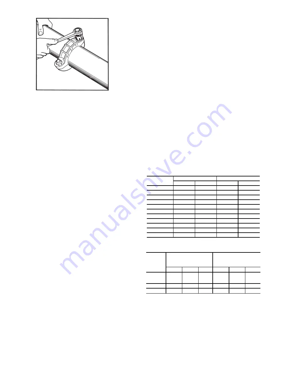
5. Alternately tighten the nuts with a wrench to draw the
coupling halves together uniformly. The joint is now
complete.
In order to minimize the water pressure drop in the system,
use as few bends as possible in the field water piping, and run
the lines as short as possible. Size the water lines according to
the available pump pressure (not necessarily the connection
size), especially on cooling tower applications. See Carrier
System Design Manual, Part 3, Piping Design. See Fig. 30-33
for pressure drops.
CONDENSER WATER CONTROL VALVE — For instal-
lations where entering condenser water temperature could be
below 65°F (18.3°C), a field-supplied control valve is required.
Operation below 65°F (18.3°C) without a valve may result in
nuisance low saturated suction alarms.
Set water regulating valve, if installed, to maintain design
head pressure. Do not adjust to compensate for high head pres-
sures caused by fouled condensers, excess refrigerant, or the
presence of non-condensables. Due to changes in water tem-
perature, it may be necessary to adjust the valve seasonally. Af-
ter adjusting for design head pressure, shut unit down. The wa-
ter regulating valve should shut off the flow of water in a few
minutes. If it does not, raise head pressure setting. Make sure
that the capillary tube from each water regulating valve is con-
nected to the proper condenser access fitting.
Provide a means for draining the system in the winter (if not
used) and for maintenance.
Water leaving the condenser is under pressure and should
not be connected directly into sewer lines. Check local codes.
EVAPORATOR DESCRIPTION — All 30MP units use a
brazed-plate heat-exchanger type evaporator. The heat ex-
changer is constructed essentially the same as the brazed-plate
condenser used on 30MPW units. See 30MPW Condenser
Description section on page 29 for more details. Similar to the
condenser, the evaporator can only be chemically cleaned. See
Fig. 30-33 for pressure drops.
EVAPORATOR PIPING — Plan evaporator fluid piping for
minimum number of changes in elevation, and for the fewest
number of bends possible. Install manual or automatic vent
valve at high points in the line. Maintain system pressure by
using a pressure tank or a combination of relief and reducing
valves. For units with water manifold option, refer to manifold
Victaulic spacer fitting kit accessory installation instructions.
A strainer with a minimum of 40 mesh must be installed
within 10 ft (3 m) of the chiller closest to the water header
inlet to prevent debris from clogging or damaging the
chiller’s heat exchangers.
See Carrier System Design Manual, Part 3, Piping Design,
for chilled fluid piping details.
The evaporator fluid inlet and outlet connections are Victau-
lic. The fluid enters at the top connection and leaves at the bot-
tom connection. Procedures for making the connections are the
same as for the 30MPW condensers. See 30MPW Condenser
section on page 29 for more details.
Run the pump for 10 minutes, then clean the strainer before
starting the unit.
An evaporator flow switch is standard on all units. This is a
thermal dispersion type switch that is installed in evaporator
fluid outlet. The switch is set to open when the evaporator fluid
flow drops below the minimum set point.
For systems with glycol concentrations greater than 30%, it
may be necessary to adjust the flow switch set point to avoid
nuisance trips. Contact your Carrier representative for the
method needed to adjust the switch.
See Table 8 for minimum flow rates. See Table 9 for mini-
mum loop volume.
The thermistors used to sense entering and leaving fluid
temperature are factory-installed in the evaporator entering and
leaving fluid nozzles.
Table
8
— Minimum Evaporator and Condenser
Flow Rates
Table 9 — Minimum Fluid Volume in Circulation
LEGEND
Fig. 29 — Install the Victaulic Coupling
a30-1245
UNIT SIZE
EVAPORATOR
CONDENSER
Gal./Min
L/s
Gal./Min
L/s
30MP016
22
1.4
22
1.4
30MP020
28
1.8
28
1.8
30MP030
43
2.7
43
2.7
30MP032
43
2.7
43
2.7
30MP040
55
3.5
55
3.5
30MP045
64
4.0
64
4.0
30MP050
70
4.5
70
4.5
30MP055
77
4.9
77
4.9
30MP060
84
5.4
84
5.4
30MP065
91
5.8
91
5.8
30MP071
104
6.7
104
6.7
30MP UNIT
SIZE
NORMAL AIR CONDITIONING
APPLICATION
gal/ton (L per kW)
PROCESS COOLING OR
LOW AMBIENT OPERATION
APPLICATION
gal/ton (L per kW)
Std Unit
HGBP
Digital
Std Unit
HGBP
Digital
016
020,030
032
6 (6.5)
4 (4.3)
3 (3.3)
10 (10.8)
10 (10.8)
6 (6.5)
040,045
3 (3.3)
3 (3.3)
3 (3.3)
6 (6.5)
6 (6.5)
6 (6.5)
050-071
6 (6.5)
4 (4.3)
—
10 (10.8)
10 (10.8)
—
HGBP —
Hot Gas Bypass


