35
FOR UNITS WITH WATER MANIFOLD — The
water
manifold is a factory-installed option, however the option
comes with the leveling kit which must be field-installed. See
leveling kit installation instructions.
For 30MP chillers, water valves are included on each water
in and out line between the 6 in. manifold and the heat ex-
changer. These valves can be used for calibration or isolation
for service.
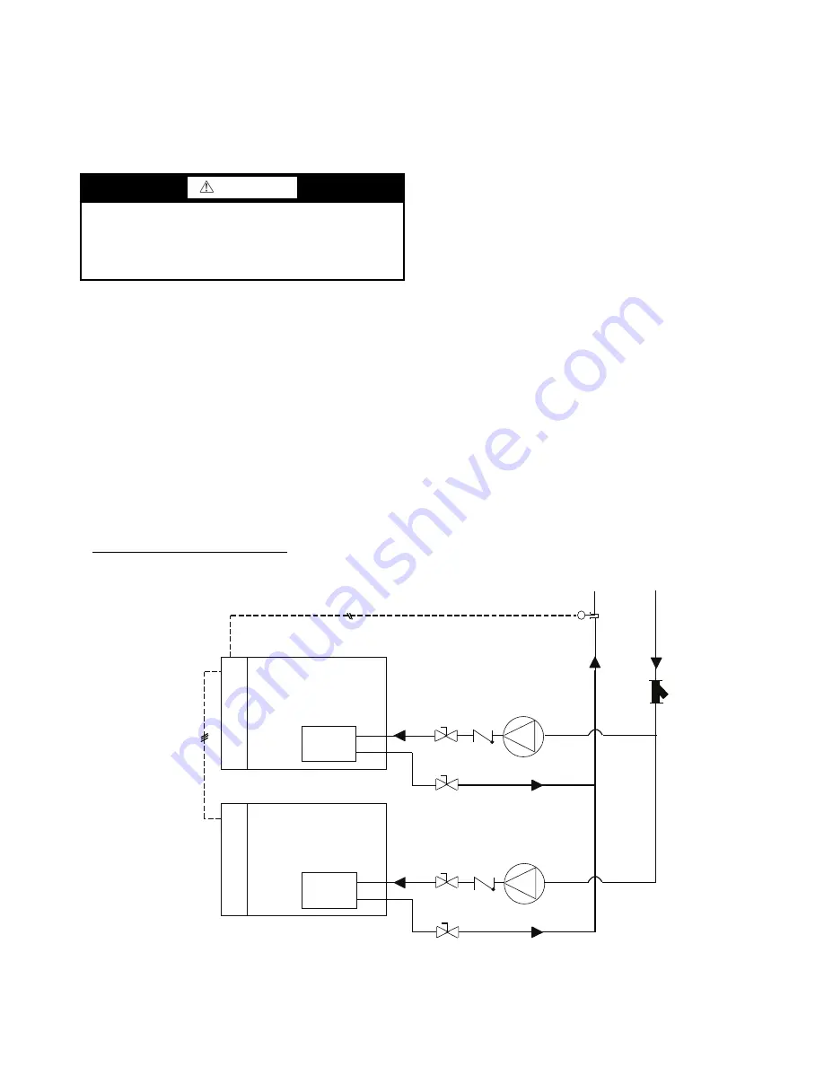
DUAL CHILLER CONTROL OPTION — If
the
dual
chiller algorithm is used, the machines must be installed in par-
allel. An additional sensor (DUAL) must be installed in the
common water line and connected to the master chiller. See
Fig. 34 for typical piping. The units must also be connected via
communications. See the Controls and Troubleshooting book
for communication connection information.
MULTI-UNIT CHILLER CONTROL ACCESSORY — If
the multi-unit chiller control accessory is used, the machines
must be installed in parallel (see Fig. 35). The accessory kit
contains the necessary chilled water temperature sensor, which
must be installed in a common water line; and connected to the
controller accessory. All chillers must be equipped with the
BACnet
1
communication option and must be connected to the
controller accessory on an MS/TP network segment in a daisy
chain configuration. See the Multi-Unit Controller Accessory
Installation Instruction for further information.
AIR SEPARATION — For proper system operation, it is
essential that water loops be installed with proper means to
manage air in the system. Free air in the system can cause
noise, reduce terminal output, stop flow, or even cause pump
failure due to pump cavitation. For closed systems, equipment
should be provided to eliminate all air from the system.
The amount of air that water can hold in solution depends
on the pressure and temperature of the water/air mixture. Air is
less soluble at higher temperatures and at lower pressures.
Therefore, separation can best be done at the point of highest
water temperature and lowest pressure. Typically, this point
would be on the suction side of the pump as the water is
returning from the system or terminals. Generally speaking,
this is the best place to install an air separator, if possible.
1. Install automatic air vents at all high points in the system.
(If the 30MP unit is located at the high point of the
system, a vent can be installed on the piping entering the
heat exchanger on the ¼-in. NPT female port.)
2. Install an air separator in the water loop, at the place
where the water is at higher temperatures and lower
pressures — usually in the chilled water return piping. On
a primary-secondary system, the highest temperature wa-
ter is normally in the secondary loop, close to the decou-
pler. Preference should be given to that point on the sys-
tem (see Fig. 36). In-line or centrifugal air separators are
readily available in the field.
It may not be possible to install air separators at the place of
lowest pressure and highest temperature. In such cases, prefer-
ence should be given to the points of highest temperature. It is
important that pipe be sized correctly so that free air can be
moved to the point of separation. Generally, a water velocity of
at least 2 feet per second will keep free air entrained and
prevent it from forming air pockets.
Automatic vents should be installed at all physically elevat-
ed points in the system so that air can be eliminated during
system operation. Provision should also be made for manual
venting during the water loop fill. It is important that the
automatic vents be located in accessible locations for
maintenance purposes, and that they be located where they can
be prevented from freezing.
WARNING
It is not recommended to use the water valves for dead end
service. If the heat exchanger is removed, it is best to install
a Victaulic fitting and end cap on the open end of the valve.
Failure to follow these instructions could result in serious
personal injury and property damage.
1. BACnet is a registered trademark of ASHRAE (American Society
of Heating, Refrigerating, and Air-Conditioning Engineers).
30MP MASTER UNIT
COOLER
30MP SLAVE UNIT
COOLER
OPTIONAL
OPTIONAL
OPTIONAL
OPTIONAL
STRAINER
DUAL THERMISTOR
AND WELL
PUMP AND CHECK VALVE
OR ISOLATION VALVE
PUMP AND CHECK VALVE
OR ISOLATION VALVE
NOTE: This is a simplified piping diagram, not all hydronic specialties are shown.
CONTROL
BOX
CONTROL
BOX
FIELD COMMUNICA
TION WIRING
T
Fig. 34 — Dual Chiller Control Option Typical Piping
a30-5627


