background image

AGAGC9PNS01D Gas Conversion Kit, Propane to Natural: Installation Instructions

Manufacturer reserves the right to change, at any time, specifications and designs without notice and without obligations.

6

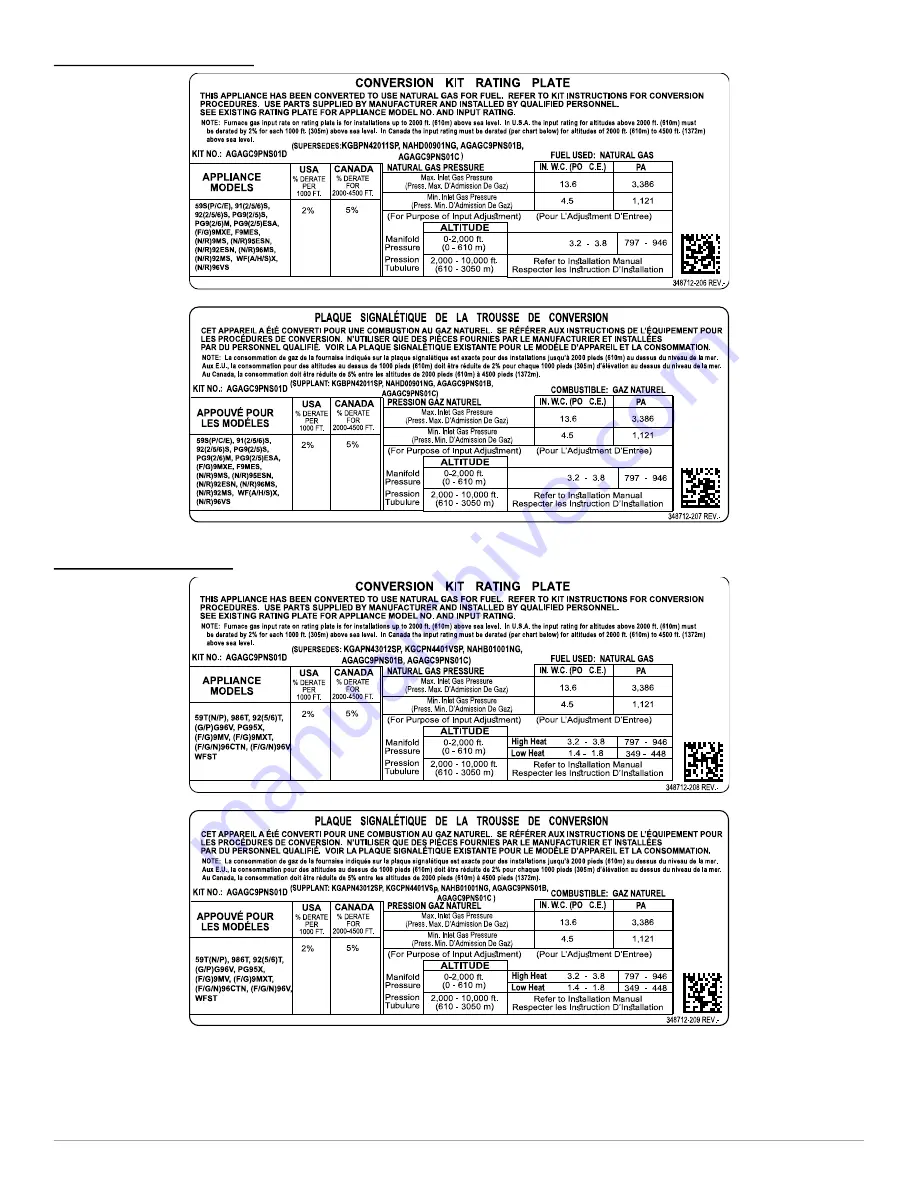
SINGLE-STAGE GAS VALVE

A221025

A221025FR

Fig. 5 – Conversion Kit Rating Plate (40,000 BTUh to 140,000 BTUh ONLY) Single-Stage Furnace

TWO-STAGE GAS VALVE

A221024

A221024FR

Fig. 6 – Conversion Kit Rating Plate (40,000 BTUh to 140,000 BTUh ONLY) Two-Stage Furnace

Summary of Contents for AGAGC9PNS01D

Page 1: ...n personal injury or death This conversion kit shall be installed by a qualified service agency in accordance with the manufacturer s instructions and all applicable codes and requirements of the authority having jurisdiction If the information in these instructions is not followed exactly a fire explosion or production of carbon monoxide could result causing property damage personal injury or los...

Page 2: ...o OFF A190014 Fig 1 Representative Furnace Drawing MANIFOLD ORIFICE BURNER REMOVAL NOTE Use a back up wrench on the gas valve to prevent the valve from rotating on the manifold or damaging the mounting to the burner box 1 Disconnect the gas pipe from gas valve and remove pipe from the furnace casing see Fig 1 2 Disconnect the connector harness from gas valve Disconnect wires from Hot Surface Ignit...

Page 3: ...line to point of intersection to find orifice size and manifold pressure settings For Modulating Furnaces Follow Steps 1 and 2 above For Step 3 use Table 6 for all sizes 20 000 BTUh Max Heat 8 000 BTUh Min Heat per burner except 60 000 BTUh models in a 21 in wide cabinet Table 7 for 60 000 BTUh models in a 21 in wide cabinet 20 200 BTUh Max Heat 8 000 BTUh Min Heat per burner 1 For both tables fol...

Page 4: ...No High Low No High Low 900 43 3 8 1 6 42 3 2 1 4 42 3 3 1 4 42 3 4 1 4 0 925 43 3 6 1 5 43 3 7 1 6 43 3 8 1 6 42 3 2 1 4 0 950 43 3 4 1 4 43 3 5 1 5 43 3 6 1 5 43 3 7 1 6 975 44 3 7 1 6 44 3 8 1 6 43 3 4 1 5 43 3 6 1 5 to 1000 44 3 5 1 5 44 3 6 1 5 44 3 8 1 6 43 3 4 1 4 1025 44 3 3 1 4 44 3 5 1 5 44 3 6 1 5 44 3 7 1 6 2000 1050 44 3 2 1 3 44 3 3 1 4 44 3 4 1 4 44 3 5 1 5 610 1075 45 3 7 1 6 45 3 ...

Page 5: ... 3 3 0 50 44 3 4 0 55 44 3 5 0 55 44 3 6 0 55 2743 775 45 3 7 0 60 44 3 2 0 50 44 3 3 0 50 44 3 4 0 55 9001 600 42 3 3 0 55 42 3 4 0 55 42 3 6 0 55 42 3 7 0 60 2744 625 43 3 7 0 60 42 3 2 0 50 42 3 3 0 55 42 3 4 0 55 650 43 3 5 0 55 43 3 6 0 55 43 3 7 0 60 43 3 8 0 60 675 44 3 7 0 60 44 3 8 0 60 43 3 4 0 55 43 3 5 0 55 10000 700 44 3 4 0 55 44 3 5 0 55 44 3 7 0 60 44 3 8 0 60 3048 725 44 3 2 0 50 ...

Page 6: ...y time specifications and designs without notice and without obligations 6 SINGLE STAGE GAS VALVE A221025 A221025FR Fig 5 Conversion Kit Rating Plate 40 000 BTUh to 140 000 BTUh ONLY Single Stage Furnace TWO STAGE GAS VALVE A221024 A221024FR Fig 6 Conversion Kit Rating Plate 40 000 BTUh to 140 000 BTUh ONLY Two Stage Furnace ...

Page 7: ...to plug the hole in the burner when the mixer screws are removed A11460 Fig 8 Mixer Screw Location REINSTALL BURNER ASSEMBLY To reinstall burner assembly 1 Attach flame sensor to burner assembly 2 Insert one piece burner in slot on sides of burner box and slide burner back in place 3 Reattach HSI wires to HSI 4 Verify igniter to burner alignment see Fig 9 Fig 10 A11405 Fig 9 Igniter Position Back ...

Page 8: ... or improper operation DO NOT use this kit if the gas valve has a green label 26 000 BTUh model on it The 26 000 BTUh model uses a different conversion kit available from your distributor CAUTION UNIT DAMAGE HAZARD Failure to follow this caution may result in unit damage The gas valve must be converted and pre adjusted before operating on propane gas If not converted and pre adjusted sooting and c...

Page 9: ...r for the modulating gas valve is very small Needle nose pliers are required to remove the jumper from the valve If the jumper is not removed the valve will not operate properly on natural gas pressures 1 Locate the round LP GAS sticker on the top of the gas valve 2 Peel the sticker off and discard 3 Note the small square opening in the top of the gas valve 4 Note the two jumper pins inside the mo...

Page 10: ...ided in kit and install in the 1 8 in 3 mm tapped inlet pressure tap opening in the gas valve DO NOT over tighten Check for gas leaks after gas supply has been turned on A170142 Fig 19 LGPS for casing wider than 14 3 16 and vent does not pass between inducer and burner assembly INSTALL MANIFOLD 1 Refer to Fig 2 and Fig 3 2 Align the orifices in the manifold assembly with the support rings on the e...

Page 11: ...rmostat connections to terminate call for heat 4 Turn furnace gas valve switch to OFF position 5 Turn gas supply manual shutoff valve to OFF position 6 Turn off furnace power supply 7 Remove manometer and on some models remove pressure tap fitting 8 On some models apply pipe dope sparingly to end of inlet gas pipe plug and install into unused end of 1 8 in 3 mm tee Use a small back up wrench on te...

Page 12: ...TIONING A C AIRFLOW SETUP SWITCHES COMMUNICATION CONNECTOR CONTINUOUS FAN CF AIRFLOW SETUP SWITCHES OUTDOOR AIR TEMP CONNECTOR HUMIDIFIER TERMINAL 24 VAC 0 5 AMP MAX FLASH UPGRADE CONNECTOR FACTORY ONLY SW4 SETUP SWITCHES SOFTWARE VERSION PART NUMBER AND DATE CODE WWYY 24 V THERMOSTAT TERMINALS PL2 HOT SURFACE IGNITER INDUCER MOTOR CONNECTOR 115 VAC L2 NEUTRAL CONNECTIONS 115 VAC L1 LINE VOLTAGE C...

Page 13: ... than one full turn with the 3 32 in hex wrench 3 Attach manometer to manifold pressure tap on gas valve see Fig 11 Fig 12 Fig 13 Fig 14 or Fig 17 4 Turn gas supply manual shutoff valve to ON position 5 Turn furnace gas valve switch to ON position 6 Check all threaded pipe connections for gas leaks 7 Turn on furnace power supply GAS INPUT RATE INFORMATION See furnace rating plates see Fig 5 Fig 6 ...

Page 14: ...crease input rate or clockwise in to increase input rate 12 Replace caps that conceal gas valve regulator adjustment screws 13 When correct input is obtained main burner flame should be clear blue almost transparent see Fig 24 14 Remove jumper across R W1 and W2 after high heat adjustment to terminate call for heat 15 Turn setup switch SW1 TT on furnace control to OFF position 16 Turn furnace gas ...

Page 15: ...sure table on Conversion Kit Rating Plate 4 To adjust the Minimum Heat manifold pressure Slowly turn the rotary adjustment switch counterclockwise to decrease manifold pressure or clockwise to increase manifold pressure 5 Turn rotary adjustment switch no more than one click per second until you obtain the required manifold pressure This adjustment will not affect the previous Maximum Heat adjustme...

Page 16: ...to Blower Access Door of furnace Date name and address of organization making this conversion are required see Fig 26 2 Attach Conversion Rating Plate Label 348712 201 204 206 207 208 or 209 to outer door of furnace see Fig 5 Fig 6 or Fig 7 3 Attach Gas Control Conversion Label 348712 202 to gas valve Do not use 348712 203 which is similar CHECKOUT 1 Observe unit operation through two complete hea...

Reviews: