


2
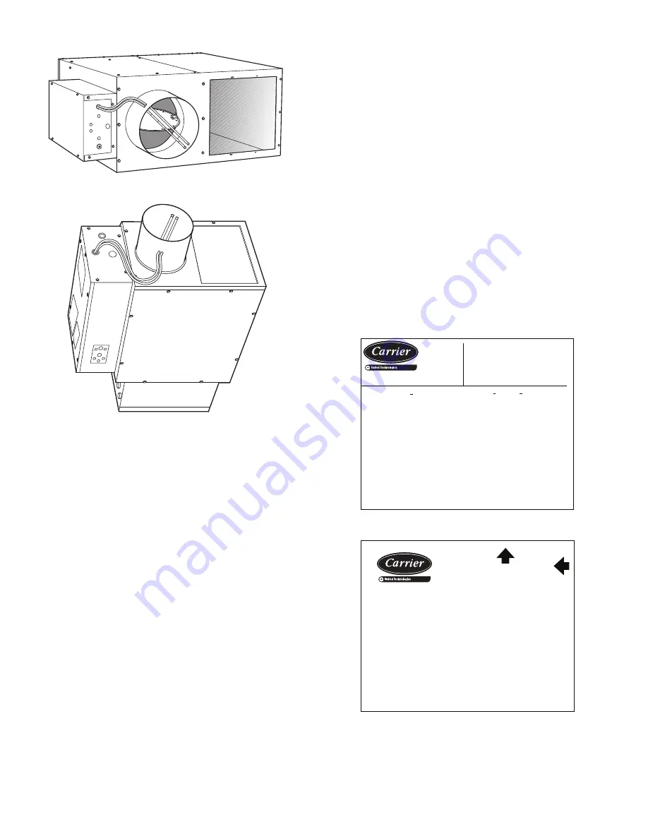
Fig. 2 — Series Flow Unit (45K Shown)
Fig. 3 — Parallel Fan Unit (45J Shown)
The 45J,M units are standard fan powered terminal units. The
45K,N units are quiet fan powered terminal units. The 45Q,R
units are low profile fan powered terminal units.
CONTROL OFFERINGS
Each 45J, 45K, 45M, 45N, 45Q, 45R unit is supplied with a
flow probe as a standard feature. This probe offers a flow aver-
aging capability and results in flow sensing capacity equal to any
competitive unit.
Control options include VAV, VVT, analog electronic, and
pressure-independent pneumatic.
Pneumatic controls are available with linear actuators and
single-function or multi-function controller. The multi-function
controller provides a simple switchover from normally open to
normally closed applications.
Electronic control units feature a factory-installed enclosure
that provides easy access for field connections.
STORAGE AND HANDLING
Inspect for damage upon receipt. Shipping damage claims
should be filed with shipper at time of delivery. Store in a
clean, dry, and covered location. Do not stack units. When
unpacking units, care should be taken that the inlet collars
and externally mounted components do not become damaged.
Do not lift units using collars, sensors, or externally mounted
components as handles. If a unit is supplied with electric or
hot water heat, care should be taken to prevent damage to
these devices. Do not lay uncrated units on end or sides. Do
not stack uncrated units over 6 ft high. Handle with care. Do
not handle control boxes by tubing connections or other ex-
ternal attachments. Tables 1-7 shows component weights.
INITIAL INSPECTION
Once items have been removed from packing, check careful-
ly for damage to duct connections, coils, or controls. File dam-
age claim immediately with transportation agency and notify
Carrier.
NOTE: Remove all packaging material and foreign material
from unit and ensure the blower wheel moves freely before
installation. Units are shipped with cardboard in both sides of
the fan inlet that MUST be removed.
Unit Identification
Each unit has 2 main labels attached to the casing. The FAN
UNIT label (Fig. 4) lists the model number, supply voltage re-
quirements, motor horsepower and overcurrent protection re-
quirements. The AIRFLOW label (Fig. 5) lists the model num-
ber, unit size, factory order number and location. The location
“tag” indicates where the unit is intended for installation. There
may be other labels attached to the unit, as options or codes may
require. Read all labels on a typical unit before attempting instal-
lation. Control boxes are assembled as indicated on the identifi-
cation label.
Contact your local Carrier representative for more in-
formation.
Fig. 4 — Fan Unit Label
Fig. 5 — Airflow Label
MODEL NO
MOTOR
45N 5
—
12
VOLT
HP
VOLT
KW
PHA
S
E
PHA
S
E
FLA(EA)
AMP
S
HZ
HZ
HZ
CODE
HEAT
TAG:
MOTOR(
S
) ARE THERMALLY PROTECTED
MIN.
S
UPPLY CIRCUIT AMP
S
MAX. FU
S
E OR HACR CIRCUIT BREAKER
S
MAX. OUTLET AIR TEMPERATURE 200 F
UNIT DE
S
IGNED TO OPERATE AT NO LE
SS
THAN 0.2 IWG
S
TATIC PRE
SS
URE.
ZERO CLEARANCE FROM UNIT, CONNECTED DUCT AND/OR PLENUM
TO COMBU
S
TIBLE MATERIAL.
REPLACEMENT LINE FU
S
E
REV:
277
1/2
480
12.0
FPB—
3
1
3
21.920
25.000
AMP
S
1
3
60
014
3
.110
60
14.4
3
25 AMP 600V
10 579600 C
FAN UNIT
ORDER:
MODEL:
LINE VLT:
S
TEP:
MIN CIR AMP:
MAX. FU
S
E OR HACR CIRCUIT BREAKER
S
MIN WIRE
S
IZE (COPPER CONDUCTOR
S
ONLY):
ITEM:
REV:
S
N:
DUCT
S
IZE:
MIN FPM:
PH:
HZ:
KW:
AMP:
CTL VOLT:
CTL VA:
INTERNAL FU
S
E
AMP
(SUITABLE FOR AT LEAST 75 DEGREES CENT.)
TAG:
599049
010
C – 599049
–
10
45J
12 X 10
0
3
75
480
0
3
60
2.50
3
.00
01
24
50
5.60
15 AMP 600V
15.00
12AWG
VAV – 05 – 01
DUCT HEATER
AIR
FLOW
UP


