background image

8

2.

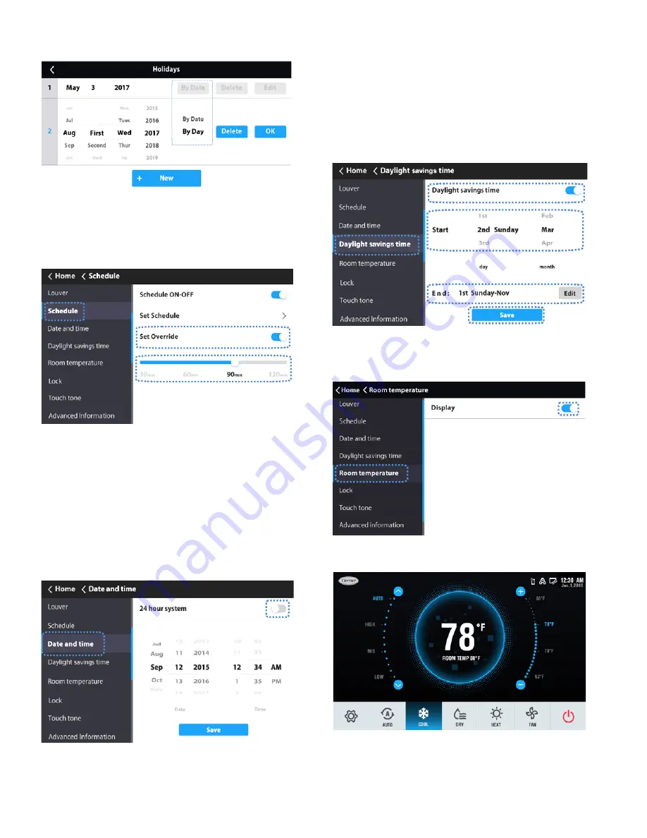
Touch “By Date” or “By Day” to change how the Date is
displayed. See Figures 21 and 22.

Setting override — 

1.

Toggle Set Override to turn override ON/OFF.

2.

Choose override time.

When Override is turned on, the available length of time

can be set to 30, 60, 90, or 120 minutes.

1.

Choose “Date and time” on the Menu interface.

2.

To use a 24 hour time format, toggle 24 hour system ON.

3.

Set the date and time by sliding the corresponding items
up and down.

4.

Touch the Save icon to save the settings.

Setting daylight savings time  — 

When enabled, 

the clock automatically moves forward one hour at 2 am on the 
specified start date. The clock goes back one hour at 2 am on 
the specified end date.

1.

Choose “Daylight savings time” on the Menu interface.

2.

Turn the “Daylight savings time” ON/OFF

.

3.

Touch the “Edit” icon.

4.

Slide the corresponding items to set the start date and end
date respectively.

5.

Touch the Save icon to save the settings.

Indoor temperature display — 

1.

Choose “Room temperature” on the menu interface.

2.

Turn the “Display” ON/OFF.

Fig. 23 — Holidays (By Day)

Fig. 25 —Set Date and Time

Fig. 26 —Daylight Savings Time

Fig. 27 —Room Temperature Display

When the display is on, the indoor temperature will be


displayed on the homepage.

Fig. 28 —Indoor Temperature Display on Homepage

Fig. 24 — Set Override

Override delay operation is only valid once. It must be reset


after operating.
The  OVERRIDE  function  will  set  the  amount  of  time  the


settings can be overridden before returning to the defined


schedule pattern.

Setting the date and time — 

Available date range: January 1, 2000 - December 31, 2037

Summary of Contents for 40VM Series

Page 1: ...sult in severe personal injury or death WARNING signifies hazards that could result in personal injury or death CAUTION is used to identify unsafe practices Table 2 Wired Controller Accessory Usage NA...

Page 2: ...he central controller locks the IDU function and the wired controller cannot use the corresponding functions of the IDU 16 Schedule Turns on when the weekly schedule is available on the wired controll...

Page 3: ...3 DIMENSIONAL DRAWING 7 1 4 4 7 8 1 1 8 Front View Side View Rear View 2 1 4 3 1 8 Fig 2 Dimensions Note All dimensions are shown in inches...

Page 4: ...indoor units see Fig 4 2 Connect field provided 24VAC power to R and C terminals 1 Remove back cover from controller as shown in Figure 5 2 Cut a hole in the wall for the 2 wire bundles Run the wires...

Page 5: ...is turned on as shown in Figure 10 Touch the corresponding fan speed text or the icon to set the fan speed See Figure 12 Fig 8 Snap controller into place Push WALL Fig 9 Turn screen on Fig 10 On Off s...

Page 6: ...E AND TIME Used to configure date and time settings and corrections DAYLIGHT SAVINGS TIME Used to adjust the clock in observance of daylight savings time ROOM TEMP Used to set display room temperature...

Page 7: ...Reset to reset all the scheduled tasks Holiday settings 1 Touch the icon from the Setting Schedule screen Figure 20 to access Holiday settings Touch to create a new Holiday Touch Edit to adjust the ex...

Page 8: ...ose Daylight savings time on the Menu interface 2 Turn the Daylight savings time ON OFF 3 Touch the Edit icon 4 Slide the corresponding items to set the start date and end date respectively 5 Touch th...

Page 9: ...rds Touch the Delete icon to delete all the error messages It displays the unit address 0 63 for indoor unit and 128 for outdoor unit and the related error code An address is not displayed when the wi...

Page 10: ...tion setting on the Service interface Fig 35 Query Dry Contact Status Fig 36 Service Menu Password Entry Fig 37 Room temp location The room temperature location can be set to Indoor unit or Wired remo...

Page 11: ...below this setting Default setting is 68F Fig 43 Thermo Off Fan Speed This determines IDU fan behavior when the zone is satisfied thermo off for both heating and cooling mode For cooling mode the defa...

Page 12: ...tal Heat Aux Heat Status These settings are used when the IDU is controlling a field provided auxiliary heat source via its ACB interface contact output Turning Aux Heat Status on enables this functio...

Page 13: ...hedules room temperature display etc Reset setting 1 Choose Reset setting on the Service interface 2 Touch the Reset icon to reset 3 Touch the YES icon to confirm the operation Fig 52 Firmware Update...

Page 14: ...tic pressure of the DC fan 0 0 in WC default 1 0 04 in WC 2 0 08 in WC 3 0 12 in WC 4 0 16 in WC 5 0 20 in WC 6 0 24 in WC 7 0 28 in WC 8 0 32 in WC 9 0 36 in WC 10 0 40 in WC 11 0 44 in WC 12 0 48 in...

Reviews: