Carrier 40VM Series Installation And Operating Instructions Manual Download Page 7

7

Enable schedule — 

Adjust the wired controller clock 

before using schedule management. 

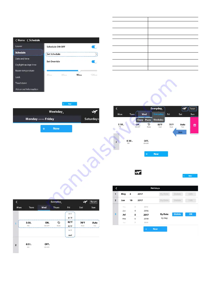
1. Choose Schedule on the menu interface.

2.

Turn the Schedule ON/OFF.

3.

Touch Set Schedule.

Setting schedule — 

1.

To add a new schedule, touch

Fig . 19 —Add Ne w S c he dule

2.

Set the scheduled time, ON/OFF mode, running mode,
temperature setpoint, and fan speed by sliding the corre-
sponding items.

3.

Touch the “Everyday” icon to switch the mode between
Everyday and Weekday.

4.

Touch to choose a day of the week. You can use the Copy
and Paste option to copy the parameters to other days of
the week.

5.

Slide the schedule from right to left to show the Delete
icon.

6.

Touch Reset to reset all the scheduled tasks.

Holiday settings — 

1.

Touch the

   icon from the Setting Schedule screen 

(Figure 20) to access Holiday settings. Touch      
to create a new Holiday. Touch Edit to adjust the 
existing or new Holiday. Figure 21 will be displayed.

Fig. 20 — Schedule

Table 6 —Daily Patterns

Parameter

Description

Day

Select the specific day for timer 

settings

Time

Set the timer time. Up to 8 timer time 

points can be set for each day

ACT

Set ON/OFF to automatic

Mode

Set the running mode if the ON 

function is automatic

Cool

When automatic or cooling mode is 

set, set the cooling temperature value

Heat

When automatic or heating mode is 

set, set the heating temperature value

Dry

When dry mode is set, set the dry 

temperature value

Fan

Set the Fan speed to automatic

Fig. 21 — Setting Schedule

Fig. 18 — Setting Schedule

Fig. 22 — Holidays (By Date)

Summary of Contents for 40VM Series

Page 1: ...sult in severe personal injury or death WARNING signifies hazards that could result in personal injury or death CAUTION is used to identify unsafe practices Table 2 Wired Controller Accessory Usage NA...

Page 2: ...he central controller locks the IDU function and the wired controller cannot use the corresponding functions of the IDU 16 Schedule Turns on when the weekly schedule is available on the wired controll...

Page 3: ...3 DIMENSIONAL DRAWING 7 1 4 4 7 8 1 1 8 Front View Side View Rear View 2 1 4 3 1 8 Fig 2 Dimensions Note All dimensions are shown in inches...

Page 4: ...indoor units see Fig 4 2 Connect field provided 24VAC power to R and C terminals 1 Remove back cover from controller as shown in Figure 5 2 Cut a hole in the wall for the 2 wire bundles Run the wires...

Page 5: ...is turned on as shown in Figure 10 Touch the corresponding fan speed text or the icon to set the fan speed See Figure 12 Fig 8 Snap controller into place Push WALL Fig 9 Turn screen on Fig 10 On Off s...

Page 6: ...E AND TIME Used to configure date and time settings and corrections DAYLIGHT SAVINGS TIME Used to adjust the clock in observance of daylight savings time ROOM TEMP Used to set display room temperature...

Page 7: ...Reset to reset all the scheduled tasks Holiday settings 1 Touch the icon from the Setting Schedule screen Figure 20 to access Holiday settings Touch to create a new Holiday Touch Edit to adjust the ex...

Page 8: ...ose Daylight savings time on the Menu interface 2 Turn the Daylight savings time ON OFF 3 Touch the Edit icon 4 Slide the corresponding items to set the start date and end date respectively 5 Touch th...

Page 9: ...rds Touch the Delete icon to delete all the error messages It displays the unit address 0 63 for indoor unit and 128 for outdoor unit and the related error code An address is not displayed when the wi...

Page 10: ...tion setting on the Service interface Fig 35 Query Dry Contact Status Fig 36 Service Menu Password Entry Fig 37 Room temp location The room temperature location can be set to Indoor unit or Wired remo...

Page 11: ...below this setting Default setting is 68F Fig 43 Thermo Off Fan Speed This determines IDU fan behavior when the zone is satisfied thermo off for both heating and cooling mode For cooling mode the defa...

Page 12: ...tal Heat Aux Heat Status These settings are used when the IDU is controlling a field provided auxiliary heat source via its ACB interface contact output Turning Aux Heat Status on enables this functio...

Page 13: ...hedules room temperature display etc Reset setting 1 Choose Reset setting on the Service interface 2 Touch the Reset icon to reset 3 Touch the YES icon to confirm the operation Fig 52 Firmware Update...

Page 14: ...tic pressure of the DC fan 0 0 in WC default 1 0 04 in WC 2 0 08 in WC 3 0 12 in WC 4 0 16 in WC 5 0 20 in WC 6 0 24 in WC 7 0 28 in WC 8 0 32 in WC 9 0 36 in WC 10 0 40 in WC 11 0 44 in WC 12 0 48 in...

Reviews: