


10
1.
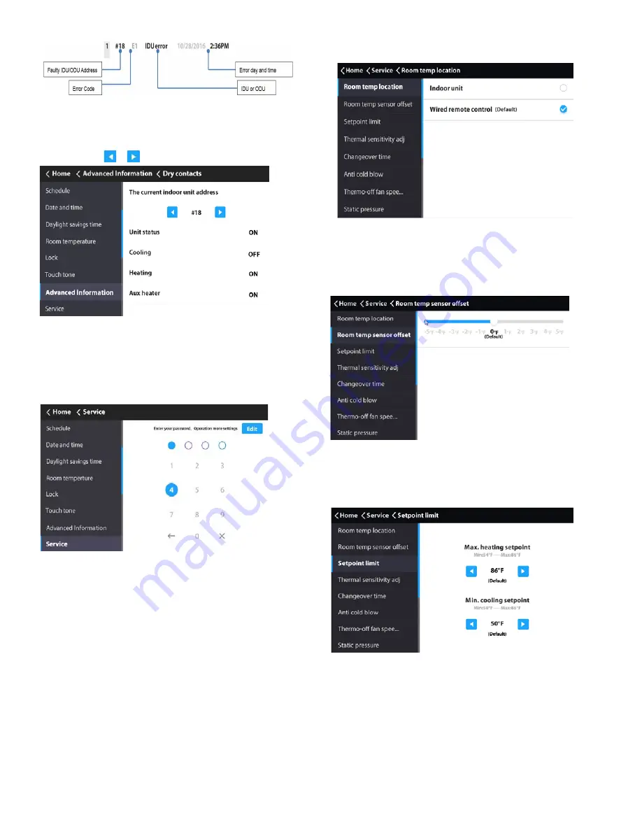
Choose “Dry contacts” on the
“Advanced Information”
interface to display status of unit and dry contact outputs.
2.
Touch the or icon to switch between IDUs.
SERVICE MENU SETTINGS
Service menu password —
1.
Choose “Service” on the “Menu” interface
.
2.
Enter the password to access the settings. The default
password is 0000.
3.
Touch the Edit icon to access password settings.
4.
Slide the submenu to view more options.
5.
Enter the correct password. The sub-options under
Service settings are displayed.
See Table 7 and the following sections for details on
additional Service Menu settings.
Setting r
oom temp location
—
Select
“Room temp
location” setting on the “Service” interface.
Fig. 35 —Query Dry Contact Status
Fig. 36 —Service Menu Password Entry
Fig. 37 —Room temp location
The room temperature location can be set to Indoor unit or
Wired remote control as required. The default setting is Wired
remote control.
Room temp sensor offset —
Select
“Room temp
sensor offset” setting on the “Service” interface.
Fig. 38 —Room temp sensor offset
The Room temp sensor offset sets the temperature compen-
sation value for the wired controller. The default value is 0
°
F.
Setpoint limit —
Select
“Setpoint limit” setting on the
“Service” interface.
Fig. 39 —Setpoint limit
The setpoint limit can set the upper limit of the temperature
range to heating and the lower limit to cooling. The default is
86
°
F for heating and 50
°
F for cooling.
Fig. 34 —Error Code/Address Field
Querying dry contact status —