background image

5

5.

Push the controller back toward the wall until it snaps into
place as shown in Figure 8.

OPERATION

Turn the screen on — 

Press the Screen ON/OFF icon

or touch the Screen.

ON/OFF setting

 — 

Touch the “ON/OFF” icon to turn the

indoor unit on or off.

Setting the mode — 

Touch the “Mode” icon in the

mode selection area to choose the mode.

NOTES:

AUTO mode is unavailable when the wired controller is


connected to a heat pump system. 
AUTO and DRY mode are unavailable when the wired


controller is connected to a VRF outside air unit.

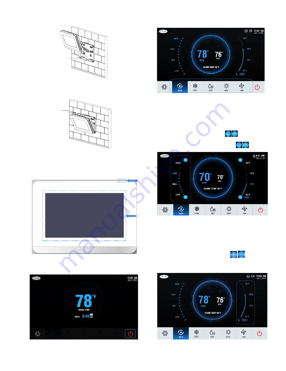
Setting the fan speed — 

The              icons will not be 

visible until the IDU is turned on as shown in Figure 10. Touch 
the corresponding fan speed text or the icon              to set the 
fan speed. See Figure 12.

Fig. 8 — Snap controller into place

Push

WALL

Fig. 9 — Turn screen on

Fig. 10 — On/Off setting

Fig. 11 — Indoor Unit Operating Icon and LED

Fig. 13 — Setting the temperature

Fig. 12 — Fan Speed Setting

Optional fan speed modes include AUTO, HIGH, MED,


and LOW. 

NOTES:

There is no AUTO fan speed when the wired controller is


connected to a VRF outside air unit. In DRY mode, the fan 
speed is permanently set to AUTO.

Setting the temperature — 

The 

 icons will not


be visible until the IDU is turned on as shown in Figure 10. See


Figure 13.

4.

Angle the controller to insert it into the bottom snap joints
of the back cover as shown in Figure 7.


Fig. 7 — Attach controller to back cover

Insert

WALL

Summary of Contents for 40VM Series

Page 1: ...sult in severe personal injury or death WARNING signifies hazards that could result in personal injury or death CAUTION is used to identify unsafe practices Table 2 Wired Controller Accessory Usage NA...

Page 2: ...he central controller locks the IDU function and the wired controller cannot use the corresponding functions of the IDU 16 Schedule Turns on when the weekly schedule is available on the wired controll...

Page 3: ...3 DIMENSIONAL DRAWING 7 1 4 4 7 8 1 1 8 Front View Side View Rear View 2 1 4 3 1 8 Fig 2 Dimensions Note All dimensions are shown in inches...

Page 4: ...indoor units see Fig 4 2 Connect field provided 24VAC power to R and C terminals 1 Remove back cover from controller as shown in Figure 5 2 Cut a hole in the wall for the 2 wire bundles Run the wires...

Page 5: ...is turned on as shown in Figure 10 Touch the corresponding fan speed text or the icon to set the fan speed See Figure 12 Fig 8 Snap controller into place Push WALL Fig 9 Turn screen on Fig 10 On Off s...

Page 6: ...E AND TIME Used to configure date and time settings and corrections DAYLIGHT SAVINGS TIME Used to adjust the clock in observance of daylight savings time ROOM TEMP Used to set display room temperature...

Page 7: ...Reset to reset all the scheduled tasks Holiday settings 1 Touch the icon from the Setting Schedule screen Figure 20 to access Holiday settings Touch to create a new Holiday Touch Edit to adjust the ex...

Page 8: ...ose Daylight savings time on the Menu interface 2 Turn the Daylight savings time ON OFF 3 Touch the Edit icon 4 Slide the corresponding items to set the start date and end date respectively 5 Touch th...

Page 9: ...rds Touch the Delete icon to delete all the error messages It displays the unit address 0 63 for indoor unit and 128 for outdoor unit and the related error code An address is not displayed when the wi...

Page 10: ...tion setting on the Service interface Fig 35 Query Dry Contact Status Fig 36 Service Menu Password Entry Fig 37 Room temp location The room temperature location can be set to Indoor unit or Wired remo...

Page 11: ...below this setting Default setting is 68F Fig 43 Thermo Off Fan Speed This determines IDU fan behavior when the zone is satisfied thermo off for both heating and cooling mode For cooling mode the defa...

Page 12: ...tal Heat Aux Heat Status These settings are used when the IDU is controlling a field provided auxiliary heat source via its ACB interface contact output Turning Aux Heat Status on enables this functio...

Page 13: ...hedules room temperature display etc Reset setting 1 Choose Reset setting on the Service interface 2 Touch the Reset icon to reset 3 Touch the YES icon to confirm the operation Fig 52 Firmware Update...

Page 14: ...tic pressure of the DC fan 0 0 in WC default 1 0 04 in WC 2 0 08 in WC 3 0 12 in WC 4 0 16 in WC 5 0 20 in WC 6 0 24 in WC 7 0 28 in WC 8 0 32 in WC 9 0 36 in WC 10 0 40 in WC 11 0 44 in WC 12 0 48 in...

Reviews: