Carrier 40VM Series Installation And Operating Instructions Manual Download Page 12

12

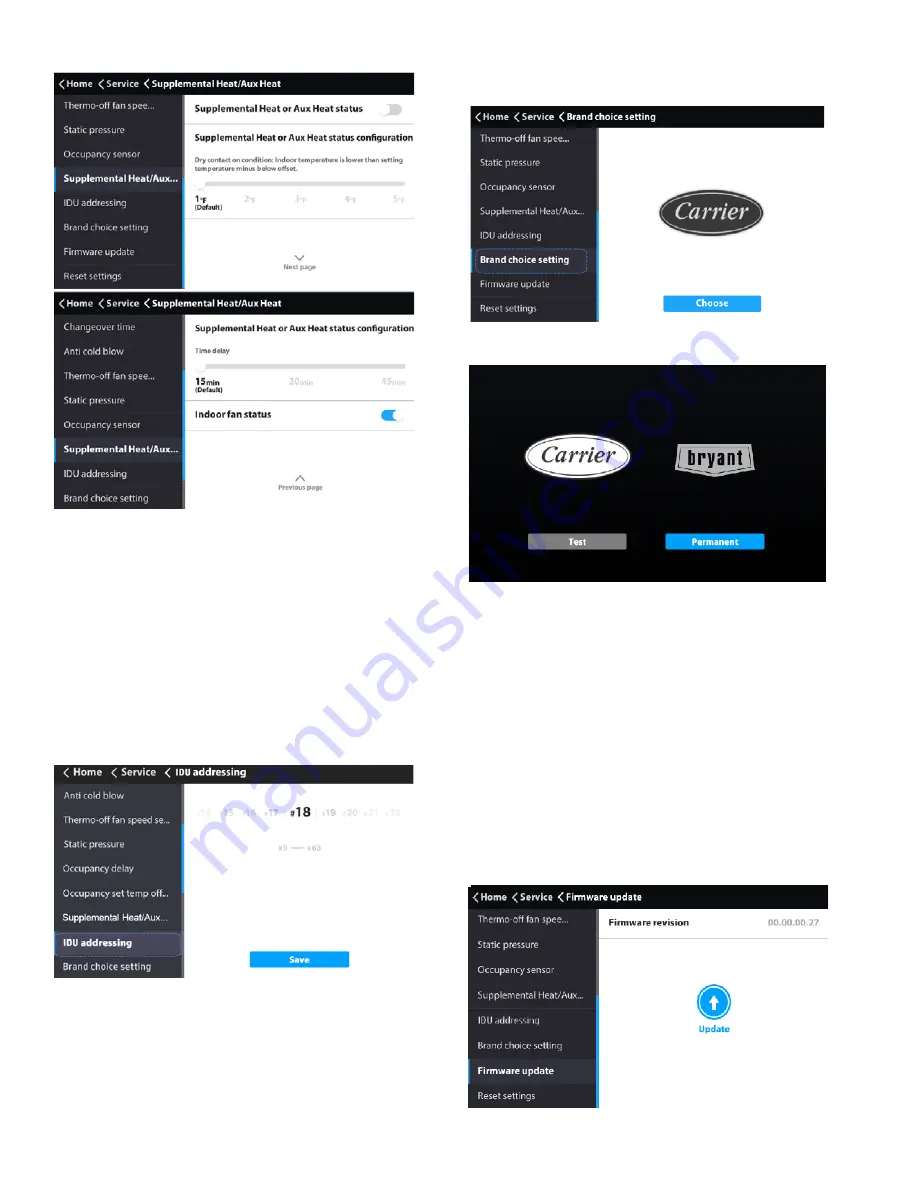
Supplemental heat/aux heat status — 

1.

Slide to choose the IDU address.

2.

Touch the Save icon to send current address to the IDU.

Brand choice setting — 

1.

Choose “Brand choice setting” on the “Service”
interface.

2.

Select either Carrier or Bryant.

1.

To use the firmware upgrade function, save the firm-
ware file and verification file in the root directory of
the USB disk.

Updating the firmware will restore the controller parameters


to 

factory  settings  while  applying  changes  associated  with  the


firmware version.

Keep the power connected during the update process.

2.

Insert the USB disk into the controller.

3.

Choose “Firmware update” on the “Service” interface.

4.

Touch the “Update” icon.

The available range of IDU address is #0 – #63.

Fig. 46 —Supplemental Heat/Aux Heat Status

These settings are used when the IDU is controlling a field-
provided auxiliary heat source via its ACB interface contact 
output.
Turning 

Aux  Heat  Status

  on  enables  this  function; 

Status


Configuration

 selects the amount of temperature differential


before triggering aux. heat output; 

Time Delay

 selects


amount of time before triggering aux heat output; and


turning 

Fan Status

 on


commands the IDU fan to run while


aux heat output is active.

Setting the indoor unit address — 

The IDU 

communication address can be set only when the wired 
controller is connected to one IDU. 

Fig. 47 —Indoor Unit Address

Fig. 48 —Brand Choice Setting

Fig. 49 —Brand Selection

“Test” is a one-time setting and will not be saved. The brand


needs to be selected again upon the next start-up.
“Permanent” indicates permanent setting and will be


effective permanently.

Firmware update — 

A USB disk in NTFS or FAT


format is required.

Fig. 50 —Firmware Update

Summary of Contents for 40VM Series

Page 1: ...sult in severe personal injury or death WARNING signifies hazards that could result in personal injury or death CAUTION is used to identify unsafe practices Table 2 Wired Controller Accessory Usage NA...

Page 2: ...he central controller locks the IDU function and the wired controller cannot use the corresponding functions of the IDU 16 Schedule Turns on when the weekly schedule is available on the wired controll...

Page 3: ...3 DIMENSIONAL DRAWING 7 1 4 4 7 8 1 1 8 Front View Side View Rear View 2 1 4 3 1 8 Fig 2 Dimensions Note All dimensions are shown in inches...

Page 4: ...indoor units see Fig 4 2 Connect field provided 24VAC power to R and C terminals 1 Remove back cover from controller as shown in Figure 5 2 Cut a hole in the wall for the 2 wire bundles Run the wires...

Page 5: ...is turned on as shown in Figure 10 Touch the corresponding fan speed text or the icon to set the fan speed See Figure 12 Fig 8 Snap controller into place Push WALL Fig 9 Turn screen on Fig 10 On Off s...

Page 6: ...E AND TIME Used to configure date and time settings and corrections DAYLIGHT SAVINGS TIME Used to adjust the clock in observance of daylight savings time ROOM TEMP Used to set display room temperature...

Page 7: ...Reset to reset all the scheduled tasks Holiday settings 1 Touch the icon from the Setting Schedule screen Figure 20 to access Holiday settings Touch to create a new Holiday Touch Edit to adjust the ex...

Page 8: ...ose Daylight savings time on the Menu interface 2 Turn the Daylight savings time ON OFF 3 Touch the Edit icon 4 Slide the corresponding items to set the start date and end date respectively 5 Touch th...

Page 9: ...rds Touch the Delete icon to delete all the error messages It displays the unit address 0 63 for indoor unit and 128 for outdoor unit and the related error code An address is not displayed when the wi...

Page 10: ...tion setting on the Service interface Fig 35 Query Dry Contact Status Fig 36 Service Menu Password Entry Fig 37 Room temp location The room temperature location can be set to Indoor unit or Wired remo...

Page 11: ...below this setting Default setting is 68F Fig 43 Thermo Off Fan Speed This determines IDU fan behavior when the zone is satisfied thermo off for both heating and cooling mode For cooling mode the defa...

Page 12: ...tal Heat Aux Heat Status These settings are used when the IDU is controlling a field provided auxiliary heat source via its ACB interface contact output Turning Aux Heat Status on enables this functio...

Page 13: ...hedules room temperature display etc Reset setting 1 Choose Reset setting on the Service interface 2 Touch the Reset icon to reset 3 Touch the YES icon to confirm the operation Fig 52 Firmware Update...

Page 14: ...tic pressure of the DC fan 0 0 in WC default 1 0 04 in WC 2 0 08 in WC 3 0 12 in WC 4 0 16 in WC 5 0 20 in WC 6 0 24 in WC 7 0 28 in WC 8 0 32 in WC 9 0 36 in WC 10 0 40 in WC 11 0 44 in WC 12 0 48 in...

Reviews: