background image

4 - SYSTEM START-UP

Keep all inspection doors closed while the unit is operating.

A safety device protecting against insufficient air flow must inserted in the fan control.

IMPORTANT: Connect all electric components to earth.

4.1 - Connecting the electric motor

The connection must be made by a qualified technician, as per the diagrams below and those included with the motor.

IMPORTANT: Before powering up the motor

, test the insulation resistance. Failure to follow this recommendation will void 

the motor warranty. 


Operating mode:

 -Before carrying out any work, disconnect and uncouple the motor or the driven machine. 

 -Measure the motor's insulation resistance before starting it up, particularly if the windings may be wet.

• 

The insulation resistance, corrected to 25°C, must exceed the reference value (100 MΩ) (measured under 500 or 1000 V CC). 

• The insulation resistance value is reduced by 50% if the room temperature increases by 20°C.

 -Fit the motor casing and discharge the cables against the casing immediately after each measurement to prevent the risk of 

electric shocks.

 -If you do not obtain the reference resistance value, the windings are too wet. They must then be dried in an oven at a temperature 

of 90°C for 12 to 16 hours, then at 105°C for 6 to 8 hours.

• 

During drying, remove the covers from the bleed holes and open the closure valves (if fitted to the motor). Remember to close 

them after drying. If the bleed caps are fixed, it is recommended to remove the terminal box flanges and covers for the drying 

operation.

• Windings which have taken in sea water must normally be rewound.

IMPORTANT: The motors are equipped with a heat protection sensor which must be connected. Check the supply voltage, 

the input current and the calibration of the protective devices.

IMPORTANT: For motors with a power of 5.5 kW or above, we recommend Y/∆ starting in order to limit the starting current 

(Id/In) and reduce the wear on the drive.


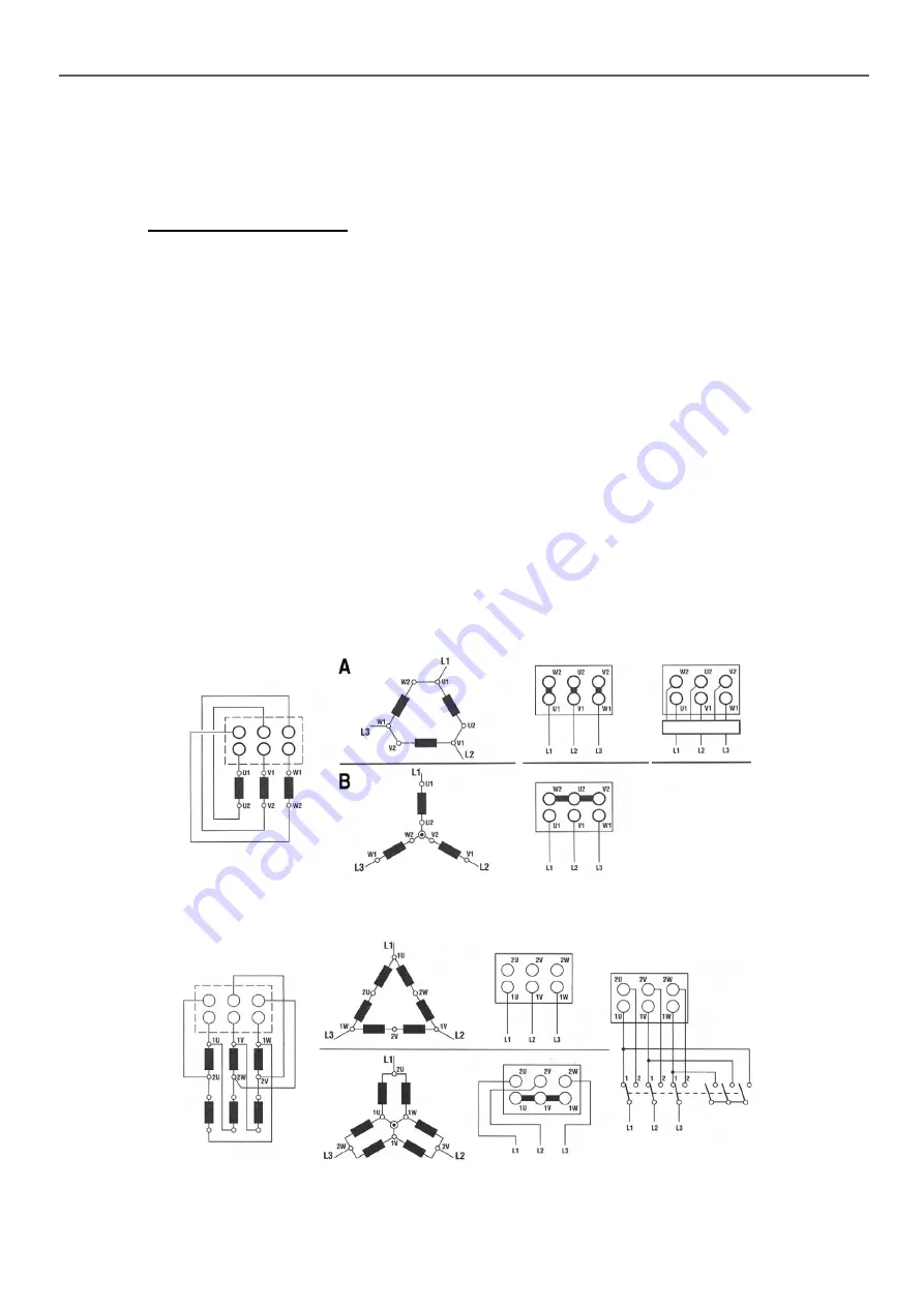
Dual voltage type motor with Y coupling, ∆ (6 terminals):    

230/400 V motor

 -

230 V supply voltage, connection (∆): diagram A.

 -400 V supply voltage: (Y) connection: diagram B.

400/690 V motor

 -

400 V supply voltage, connection (∆): diagram A.

 -690 V AC supply voltage (for P>5.5 kW), connection (Y): diagram B.


Dahlander dual-speed motor or motor with reversible poles, 6 terminals.

These diagrams apply to three-phase, 3000/1500 rpm and 1500/750 rpm motors.

Low

speed

(LS)

High

Speed

(HS)

LS and HS for “2” contacts

17

Summary of Contents for 39CZ

Page 1: ...INSTALLATION OPERATION AND M A I N T E N A N C E I N S T R U C T I O N S Translation of the original document Air handling unit 39CZ...

Page 2: ...2...

Page 3: ...rs 19 5 4 Humidifiers 20 5 5 Fan motor assembly 21 5 6 Sound attenuator 21 5 7 Heat recovery units 21 5 8 Preventive maintenance 22 5 9 Cleaning the units 22 6 WARRANTIES 23 6 1 Duration of warranty o...

Page 4: ...tc are allowed They should never be used for any other purpose storage support etc 1 1 General safety instructions The following must be performed before any work on the air handling unit The power mu...

Page 5: ...C Section number A1 A2 A9 multi section unit A second unit may bear the markings B1 B2 B9 The numbers 1 2 and 3 do not necessarily indicate the order of assembly refer to the dimensional drawing A9 B...

Page 6: ...imum angle of 60 Important Make sure that the spreader beam is sufficiently large so that the straps do not press against the unit and the steel tubes are immobilised while moving the unit B B B Limit...

Page 7: ...PORTANT Make sure to ground all electric components NOTE For large units plate wheel recovery units mixing units etc the transport brackets located at the corners must be removed upon delivery 3 2 Ass...

Page 8: ...n must not be mechanically fastened to the bottom section Its weight will keep it in place IMPORTANT Before tightening the brackets seal the sections with a gasket or caulking B Fig A Fig B Fig C C B...

Page 9: ...bly with stacked casings A and B The unit can be assembled in one of two of ways depending on its size 25 to 75 units affix the feet of block B to the intermediate panel C using two TH 6x20 screws Hol...

Page 10: ...rs must be protected by a roof Fig 1 or overhang Fig 2 These components are generally delivered in kits and adapted to each configuration Overhang Fitting the roofs Affix the gasket B along the length...

Page 11: ...ing gasket 4 around the edge of the canopy and apply mastic if necessary Fit the screen and the canopy and affix the assembly to the unit using diameter 5 53 sheet metal screws and washers The canopy...

Page 12: ...n the unit Other filters are supplied in their packing B C C D E B G4 filter C HPS filter D HPR or carbon filter E HEPA filter 3 4 Water and direct expansion coil Do not remove the protective caps unt...

Page 13: ...er If the outlet temperature on the frost protection coil is below 15 C use a constant volume control valve to prevent the frost protection alarm being triggered and frost forming on the coil Cooling...

Page 14: ...le Max current 27 A Connect these wires to the designated terminals and the terminals on the manual and automatic reset thermostats depending on unit inside the box The stages power connection termina...

Page 15: ...ess the opening limit switch is tripped If a two speed motor is used the shift from high to low speed should be timed to avoid a braking effect 3 7 Fan motor assembly The spring mounted fan motor asse...

Page 16: ...e Alignment axis B C Fit the belts Tension the belts as instructed in the previous section IMPORTANT If changes are made to the drive make sure that it is compatible with the fan motor assembly motor...

Page 17: ...rence resistance value the windings are too wet They must then be dried in an oven at a temperature of 90 C for 12 to 16 hours then at 105 C for 6 to 8 hours During drying remove the covers from the b...

Page 18: ...m speed of the rotating parts from being exceeded or the motor from being overloaded Eliminate the frequencies producing resonances by checking the operation of the fan one frequency at a time Fit Du...

Page 19: ...hat the screen is positioned on the discharge air side HPS bag filters M5 M6 F7 F8 F9 Bag filters last a long time but are non regenerative They must be replaced when they are clogged Check the condit...

Page 20: ...electrodes prevent normal current flow alarm E06 E08 Disassemble the cylinder as follows Press the manual drain button to completely empty the water in the cylinder Remove the cylinder steam hose Disc...

Page 21: ...ns We recommend lubricating other bearings once every 7 000 hours of operation Drives Refer to section 3 on the fan motor assemblies 5 6 Sound attenuator No special servicing is required for the sound...

Page 22: ...he coil varies by operating conditions HUMIDIFIER see humidifier manual This table relates to standard use of our units and is provided for guidance only Servicing frequency rates must therefore be ad...

Page 23: ...oating by impacts air pollution animals or mildew moss and mould Damage caused by natural phenomena such as hail Damage caused by accidents 6 2 Duration of the air handling unit warranty CARRIER provi...

Page 24: ...pply to the presence of a flow rate detected by a sensor In all cases refer to the general information section of this manual to the specific manuals for the ATEX components built into the unit and li...

Page 25: ...s in complete safety There are two different types to be taken into consideration Type A Tools liable to only produce single sparks when used such as screwdrivers spanners or impacts wrenches for exam...

Page 26: ...8 MEANING OF THE PICTOGRAMS Water outlet Water inlet Air flow direction Monitor the cleanliness of the filters Condensate drain siphon Electric heater Grounding compulsory 26...

Page 27: ...Conformity This unit complies with the requirements of Supply of Machinery Safety Regulations 2008 Electromagnetic Compatibility Regulations 2016 The Restriction of the Use of Certain Hazardous Substa...

Page 28: ...01 12 2021 Replaces N EN7505284 00 04 2016 Manufacturedby CarrierS C S RtedeThil 01120Montluel France The manufacturer reserves the right to change the product specifications without notice Printed in...

Reviews: