


5
General information and characteristics
ELECTRICAL SHOCK HAZARD
Failure to follow this warning could result in personal
injury or death.
Before connecting any wiring to the Room
Controller, turn off all power to the unit that will supply
power to the Room Controller.
!
WARNING
P
G
C
P
G
C
40KMC and 40KMQ Cassette Family
1
2
A
Red
Black
White
Remote connector
(J5) 5 pins
3
4
B
Diagram 1:
Connection diagram for the following units:
A Indoor unit
B Room Controller
1. Main electronic card
2. 4 pins terminal block placed on external control box
3. Wires supplied by the installer
4. Terminal block in the Room Controller
S
Loosen the screws of terminals P (DC Power), G
(GROUND) and C (SIGNAL) on the indoor unit and
Room Controller terminal blocks.
S
As shown in diagram 1 connect the indoor unit terminal
block to the Room Controller terminal block.
P
G
C
P
G
C
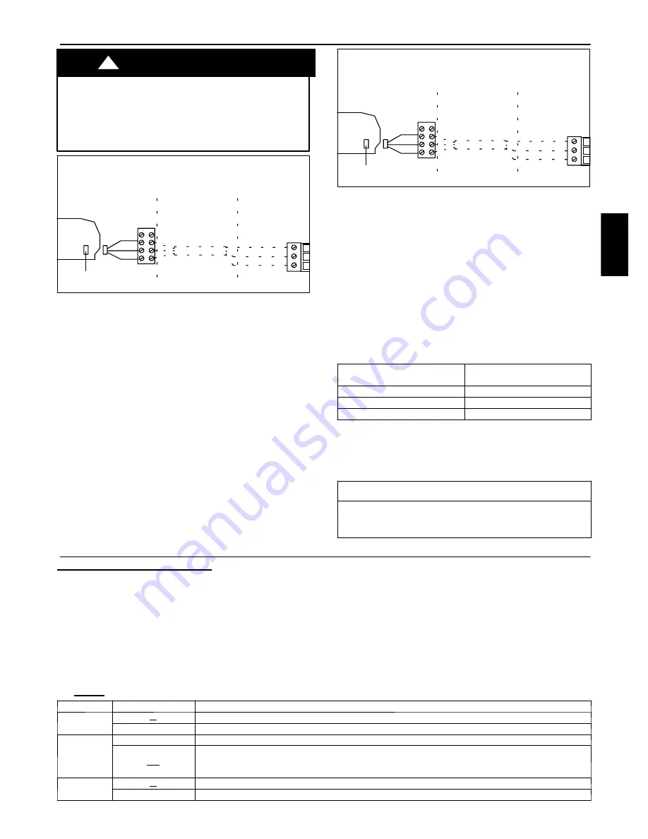
40QNC and 40QNQ Highwall Family
1
2
A
Red
Black
White
Remote connector
(J5) 5 pins
3
4
B
Diagram 2:
Connection diagram for the following units:
A Indoor unit
B Room Controller
1. Main electronic card
2. 4 pins terminal block placed on external control box
3. Wires supplied by the installer
4. Terminal block in the Room Controller
S
Loosen the screws of terminals P (DC Power), G
(GROUND) and C (SIGNAL) on the indoor unit and
Room Controller terminal blocks.
S
By means of the screw provided with the Room
Controller Kit, secure the auxiliary terminal block (3
poles) to the main terminal box (6 poles).
S
As shown in diagram 2.
Cables of auxiliary
terminal block
Room Controller
terminal block
Red
P
Black
G
White
C
S
Remove the cables from connector J5 inside the unit on
the electronic card to connect the cables supplied with
the Room Controller. Connect the indoor unit terminal
block to the Room Controller terminal block in the same
way as shown in diagram 2.
Wiring Materials required
(supplied by installer)
•
1 small screwdriver.
•
Standard Double insulated wire recommended.
Unit Configuration
Room Controller Configuration Setup
To enter installer setup, hold the “MODE“ button down for 5
seconds. After 5 seconds, a “10“ will appear. This indicates that the
user is setting the first software configuration item. To check the
value of configuration item 10, press the “MODE” button. The
value of the Heat/Cool vs Cooling only remote configuration will
be displayed along with the “SET TEMP” icon to indicate that the
number displayed is the configuration data. To change the
Heat/Cool vs Cooling only remote Configuration, use the
“UP“/”DOWN“ buttons. To move to the next setting, press the
“MODE“ button again and the “10“ will be
displayed. Press the up button and the display will change to “11”.
The mode button will toggle the display between the software
configuration index (i.e. “10“, “11“, etc.) and the configuration
value. The “UP”/”DOWN“ buttons will change either the index or
the value, which ever is displayed at the time. Press the ”FAN”
SPEED button to exit Configuration Setup Mode. This mode will
exit automatically after 10 seconds of no buttons being depressed.
Once a configuration value is changed, the last value displayed will
be the new configuration value for the Room Controller.
The only way to abort a configuration change is to change the
value back to its original value.
The
BOLD
values are the default values from the factory.
Item
Value
Description
10
H
Heat/cool remote
C
Cooling only remote
11
On
Room Thermistor Override Active.
OF
Control and display room air temperature at the Room Controller control.
Room Thermistor Override Inactive
. Do not display room air temperature at the Room Controller and
control to New Modular DFS room air thermistor(s).
12
C
Temperatures displayed in degrees C
F
Temperatures displayed in degrees F
33MC
--
U
RC


