


24
5.4 - Recommended wire sections
Wire sizing is the responsibility of the installer, and depends on
the characteristics and regulations applicable to each installation
site. The following is only to be used as a guideline, and does not
make Carrier in any way liable. After wire sizing has been
completed, using the certified dimensional drawing, the installer
must verify the appropriate means of connection and define any
modifications necessary on site.
The connections provided as standard for the customer-supplied
power supply cables are designed for the number and type of
wires, listed in the table below.
The calculations of favourable and unfavourable cases are
performed by using the maximum possible current for each unit
fitted with a hydraulic kit (see the tables of electrical data notes
for the unit and the hydraulic module).
The study includes the standardised installation cases according
to IEC 60364: cables with PVC (70°C) or XLPE insulation
(90°C) with copper core; routing in accordance with table 52C
of the standard. The maximum ambient temperature is 45°C.
The maximum length mentioned is calculated to limit the voltage
drop to 5 %.
IMPORTANT: Before connecting the main power cables (L1
- L2 - L3), always check 3 phases are in the correct order
(clockwise) before proceeding to the connection on the main
disconnect switch.
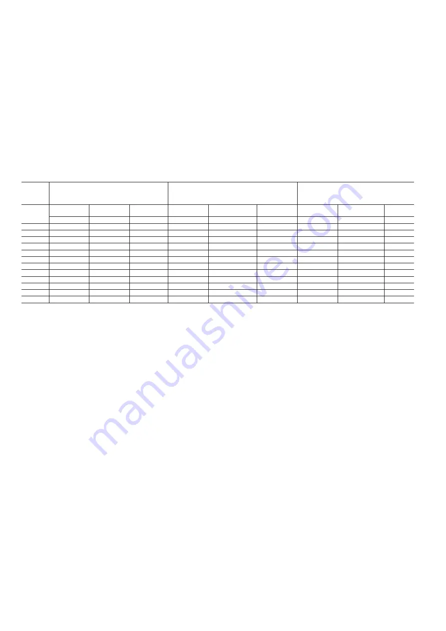
Table of minimum and maximum cable sections (per phase) for connection to 30RQM/30RQP units
Max. connectable section
(1)
Calculation of favourable case:
- Suspended overhead line (standardised routing no. 17)
- Cable with XLPE insulation
Calculation of unfavourable case:
- Conductors in ducts or multi-conductor cables in
closed conduits (standardised routing no. 41)
- Cable with PVC insulation
30RQM/
30RQP
Standard lug
Narrow lug
Recommended
max lug width
Section
(2)
Max length for a
voltage drop < 5%
Cable type
(3)
Section
(2)
Max length for a
voltage drop < 5%
Cable type
(3)
mm² (per phase) mm² (per phase) mm
mm² (per phase) m
-
mm² (per phase) m
-
160
2x70
2x95
21
1 x 50
200
XLPE Copper
2 x 50
388
PVC Copper
180
2x70
2x95
21
1 x 50
180
XLPE Copper
2 x 50
358
PVC Copper
210
2x70
2x95
21
1 x 70
210
XLPE Copper
2 x 70
380
PVC Copper
230
2x70
2x95
21
1 x 70
190
XLPE Copper
2 x 70
350
PVC Copper
240
2x70
2x95
21
1 x 70
180
XLPE Copper
2 x 70
350
PVC Copper
270
2x70
2x95
21
2 x 35
160
XLPE Copper
2 x 95
400
PVC Copper
310
2x95
2x185
21
2 x 50
200
XLPE Copper
2 x 120
430
PVC Copper
330
2x95
2x185
24.5
2 x 50
190
XLPE Copper
2 x 150
490
PVC Copper
380
2x95
2x185
24.5
2 x 70
220
XLPE Copper
2 x 150
420
PVC Copper
430
2x95
2x185
24.5
2 x 70
190
XLPE Copper
2 x 185
430
PVC Copper
470
2x240
2x240
37
2 x 95
230
XLPE Copper
2 x 240
470
PVC Copper
520
2x240
2x240
37
2 x 95
210
XLPE Copper
2 x 240
430
PVC Copper
Notes:
(1) Connection capacities actually available for each machine. These are defined according to the connection terminal size, the electrical box access opening dimensions and the available space
inside the electrical box.
(2) Selection simulation result considering the hypotheses indicated.
(3) If the maximum calculated section is for an XLPE cable type, this means that a selection based on a PVC cable type can exceed the connection capacity actually available. Special attention must
be given to selection.
The protection against direct contact at the electrical connection point is compatible with the addition of terminals extension. The installer must determine whether these are necessary based on
the cable sizing calculation.