


14
Condenser coil
We recommend, that finned coils are inspected regularly to
check the degree of fouling. This depends on the environment
where the unit is installed, and will be worse in urban and
industrial installations and near trees that shed their leaves.
For coil cleaning proceed as follows:
•
Remove fibres and dust collected on the condenser face
with a soft brush (or vacuum cleaner).
•
Clean the coil with the appropriate cleaning agents.
We recommend TOTALINE products for coil cleaning:
Part No. P902 DT 05EE: traditional cleaning method
Part No. P902 CL 05EE: cleaning and degreasing.
These products have a neutral pH value, do not contain
phosphates, are not harmful to the human body, and can be
disposed of through the public drainage system.
Depending on the degree of fouling both products can be used
diluted or undiluted.
For normal maintenance routines we recommend using 1 kg
of the concentrated product, diluted to 10%, to treat a coil
surface of 2 m
2
. This process can either be carried out with
a TOTALINE applicator gun (part No. TE01 WA 4000EE)
or using a high-pressure spray gun in the low-pressure position.
With pressurised cleaning methods care should be taken not to
damage the coil fins. The spraying of the coil must be done:
- in the direction of the fins
- in the opposite direction of the air flow direction
- with a large diffuser (25-30°)
- at a distance of 300 mm.
The two cleaning products can be used for any of the following
coil finishes: Cu/Cu, Cu/Al, Cu/Al with Polual, Blygold and/or
Heresite protection.
It is not necessary to rinse the coil, as the products used are pH
neutral. To ensure that the coil is perfectly clean, we
recommend rinsing with a low water flow rate. The pH value
of the water used should be between 7 and 8.
WARNING: Never use pressurized water without a large
diffusor. Concentrated and/or rotating water jets are strictly
forbidden.
Correct and frequent cleaning (approximately every three
months) will prevent 2/3 of the corrosion problems.
Fan motor replacement
This presents no special problems. The work is done from
above the unit.
•
Remove the grille with its support air duct assembly.
•
Remove the fan shaft protection cap.
•
Pull the fan from the shaft using a FACOM U35, or
similar, hub puller.
•
Unscrew the fan motor fixing bolts.
Remove only the lower bolts to prevent the motor from
falling.
•
Withdraw the fan motor.
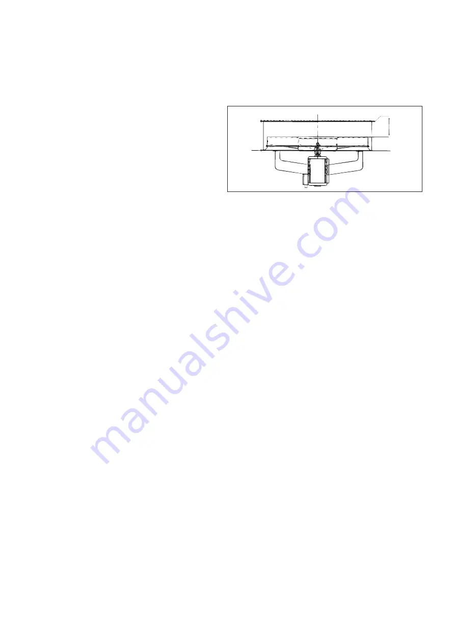
Installation is in the reverse order. Take care not to damage the
plastic components when installing the fan and position the fan
to maintain a clearance of 117 + 0/-2 mm between the upper
edge of the fan and the upper edge of the volute.
CAUTION: On unit sizes 30GH/GZ 040-245 the fan rotation is
counter clockwise, viewed from above.
30GH/GZ 040-245 fan
Fan motor protection
All units are equipped with a fan protection circuit breaker.
Refrigerant circuit
Thermal expansion valve (TXV)
The function of the thermal expansion valve is to control the
flow of liquid refrigerant. The valve is controlled by a sensor
bulb in the compressor suction line. It is factory set to maintain
refrigerant superheat of 4 K.
This setting should not be changed unless absolutely necessary.
Filter-drier
The filter-drier keeps the circuit clean and free of moisture. The
sight glass indicates when it is necessary to change the cartridge
in the filter-drier. A temperature difference between the inlet
and the outlet of the filter-drier indicates fouling of the drier.
NOTE: The unit must run for at least 12 hours before it can
give an accurate indication, because only with the unit running
is the indicator in continuous contact with the refrigerant.
Liquid line service valve
This valve provides, in each circuit, a liquid refrigerant charging
port and, in conjunction with the compressor discharge line
valves, enables liquid refrigerant to be pumped to the high
pressure side of the system.
117 +0/-2
Maximum
clearance


