background image

17

0

10

20

30

40

50

60

70

80

90

0

20

40

60

80

100

120

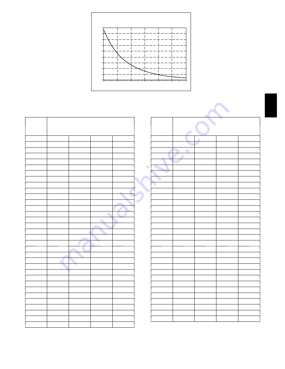
TEMPERATURE (DEG. F)

RESISTANCE (KOHMS)

THERMISTOR CURVE

A91431

Fig. 16

---

Resistance vs. Temperature Chart

Table 4—Required Liquid---Line Temperature

Liquid

Pressure

at Service

Valve

Required Subcooling Temperature

(

°

F)

(PSIG)

5

10

15

20

174

56

51

46

41

181

58

53

48

43

188

61

56

51

46

195

63

58

53

48

202

65

60

55

50

209

67

62

57

52

216

69

64

59

54

223

71

66

61

56

230

73

68

63

58

237

75

70

65

60

244

77

72

67

62

251

79

74

69

64

258

81

76

71

66

265

82

77

72

67

272

84

79

74

69

279

86

81

76

71

286

88

83

78

73

293

89

84

79

74

300

91

86

81

76

307

93

88

83

78

314

94

89

84

79

321

96

91

86

81

328

97

92

87

82

335

99

94

89

84

342

100

95

90

85

349

102

97

92

87

356

103

98

93

88

363

105

100

95

90

370

106

101

96

91

377

107

102

97

92

384

109

104

99

94

391

110

105

100

95

Liquid

Pressure

at Service

Valve

Required Subcooling Temperature

(

°

F)

(PSIG)

5

10

15

20

398

112

107

102

97

405

113

108

103

98

412

114

109

104

99

419

115

110

105

100

426

117

112

107

102

433

118

113

108

103

440

119

114

109

104

447

120

115

110

105

454

122

117

112

107

461

123

118

113

108

468

124

119

114

109

475

125

120

115

110

482

126

121

116

111

489

127

122

117

112

496

129

124

119

114

503

130

125

120

115

510

131

126

121

116

517

132

127

122

117

524

133

128

123

118

531

134

129

124

119

538

135

130

125

120

545

136

131

126

121

552

137

132

127

122

559

138

133

128

123

566

139

134

129

124

573

140

135

130

125

580

141

136

131

126

587

142

137

132

127

594

143

138

133

128

601

144

139

134

129

608

145

140

135

130

25H

PA

Summary of Contents for 25HPA Performance Series

Page 1: ...ements 3 Step 4 Operating Ambient 3 Step 5 Elevate Unit 3 Step 6 Install TXV 3 4 Step 7 Make Piping Connections 5 7 Step 8 Make Electrical Connections 7 8 Step 9 Compressor Crankcase Heater 8 Step 10...

Page 2: ...h a suitable warning label INSTALLATION RECOMMENDATIONS NOTE In some cases noise in the living area has been traced to gas pulsations from improper installation of equipment 1 Locate unit away from wi...

Page 3: ...23 3 4 36 1 2 X 40 9 5 8 6 13 16 28 3 4 A05177 Fig 3 Tiedown Knockout Requirements On rooftop applications locate unit at least 6 in above roof surface STEP 4 Operating Ambient The minimum outdoor ope...

Page 4: ...R 22 Indoor Coil 1 Pump system down to 2 psig and recover refrigerant 2 Remove coil access panel and fitting panel from front of cabinet 3 Remove TXV support clamp using a 5 16 in nut driver Save the...

Page 5: ...or coil are exposed to atmosphere they must be evacuated to 500 microns to eliminate contamination and moisture in the system Table 1 Accessory Usage Accessory REQUIRED FOR LOW AMBI ENT APPLICATIONS B...

Page 6: ...ilure to follow this caution may result in equipment damage or improper operation Service valves must be wrapped in a heat sinking material such as a wet cloth while brazing CAUTION UNIT DAMAGE HAZARD...

Page 7: ...tdoor unit has not shifted during shipment Ensure tubes are not rubbing against each other or any sheet metal Pay close attention to feeder tubes making sure wire ties on feeder tubes are secure and t...

Page 8: ...contact with tubing sheet metal etc STEP 9 Compressor Crankcase Heater When equipped with a crankcase heater furnish power to heater a minimum of 24 hr before starting unit To furnish power to heater...

Page 9: ...properly start up system 1 After system is evacuated fully open liquid and vapor service valves 2 Unit is shipped with valve stem s closed and caps installed Replace stem caps after system is opened...

Page 10: ...vice port 3 Measure liquid line temperature by attaching an accurate thermistor type or electronic thermometer to liquid line near outdoor coil 4 Refer to unit rating plate for required subcooling tem...

Page 11: ...ing Operation This product utilizes either a standard indoor thermostat or Infinity communication User Interface With a call for cooling the outdoor fan reversing valve and compressor are energized Wh...

Page 12: ...ater than or equal to 100 deg F S Fifteen second delay at termination of defrost before the auxiliary heat W2 is de energized S Twenty second delay at termination of defrost before the outdoor fan is...

Page 13: ...ches on the unit control board or in the Infinity control if used The Infinity Control selection overrides the control board dip switch settings Auto defrost is available with Infinity communicating c...

Page 14: ...he wiring label diagram This is a 24vac output that is energized whenever the compressor is energized It closes in the compressor off mode to prevent refrigerant migration into the unit through the li...

Page 15: ...cooling continues the control will energize the compressor contactor every 15 minutes If the thermal protector closes at the next 15 minute interval check the unit will resume operation If the therma...

Page 16: ...ir flow Control Fault 45 Outdoor unit control board has failed Control board needs to be replaced Brown Out 24 v 46 The control voltage is less than 15 5v for at least 4 seconds Com pressor and fan op...

Page 17: ...89 84 342 100 95 90 85 349 102 97 92 87 356 103 98 93 88 363 105 100 95 90 370 106 101 96 91 377 107 102 97 92 384 109 104 99 94 391 110 105 100 95 Liquid Pressure at Service Valve Required Subcooling...

Page 18: ...with 550 psig low side retard S Use hoses with 700 psig service pressure rating S Leak detectors should be designed to detect HFC refrigerant S Puron refrigerant as with other HFCs is only compatible...

Reviews: