background image

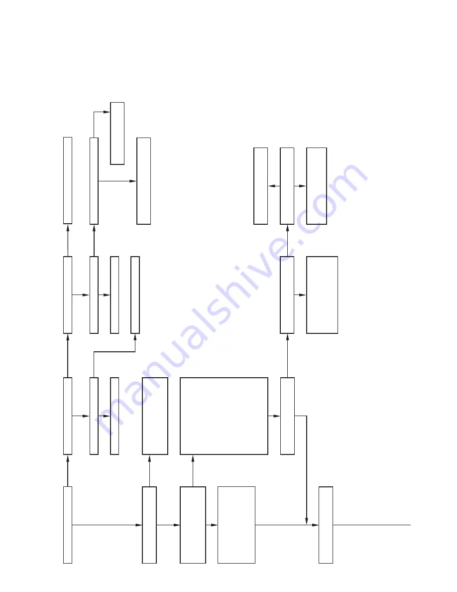
Is circuit breaker closed?

Close door switch and go to start.

Is red LED status light on?

Is door switch closed?

Is red LED status light blinking

rapidly without a pause?

Is there 1

15v going to switch?

Replace door switch.

Replace control center

.

Replace transformer

.

Is red LED status light blinking

ON/OFF slowly with a

combination of short and long

flashes?

Check for correct line voltage

polarity

. If units are twinned,

check for proper low-voltage

(24v) transformer phasing.

Check for previous fault by

momentarily shorting the 

TEST

terminal and the C terminal until

the LED goes out. LED will flash

the status code of any previous

fault or the code No. 1

1

 (1 short

and 1 long flash) if no previous

fault. 

After the control repeats the

code 3 times, the control will go

through a brief component test

sequence. 

The inducer will start

and run for the entire component

test. 

The HSI, blower motor heat

speed, and blower motor cool

speed will run for 10-15 sec each.

Determine status code. 

The

status code is a 2 digit number

with the first digit determined by

the number of short flashes and

the second digit by the number of

long flashes.

W

as there a previous fault code

other than No. 1

1

?

Does control respond to W

Y

,

or G 24-vac thermostat signals?

Run system through a heating or

cooling cycle to check operation.

Status codes are erased after 48

hrs or whenever power (1

15v

or 24v) is interrupted.

Go to section with status code

determined.

Is there 1

15v at L1 and L2?

Close circuit breaker and

go back to start.

Check for continuity in wire from circuit

breaker to furnace.

NO

NO

NO

NO

NO

NO

YES

YES

YES

YES

YES

YES

YES

NO

NO

YES

YES

YES

ST

AR

T

Is there 24v at SEC-1 and SEC-2?

NO

Is 24 vac present at W

Y

, or G

terminals on the control?

Replace control if it does not

respond to 24-vac signal at W

Y

,

or G screw terminals.

Check room thermostat or

interconnecting cable.

YES

NO

NO

12

Summary of Contents for 170 Series

Page 1: ... safety codes including the National Fuel Gas Code NFGC NFPA 54 1999 ANSI Z223 1 1999 NFPA 90B In Canada refer to the CAN CGA B149 1 and 2 M95 National Standard of Canada Natural Gas and Propane Installation Codes NSCNGPIC Wear safety glasses and work gloves Have fire extinguisher available during start up and adjustment procedures and service calls Recognize safety information This is the safety ...

Page 2: ...l sources may also be used to prevent ESD damage CARE AND MAINTENANCE For continuing high performance and to minimize possible equip ment failure it is essential that periodic maintenance be performed on this equipment Consult your local dealer as to the proper frequency of maintenance and the availability of a maintenance contract Never store anything on near or in contact with the furnace such a...

Page 3: ...and let dry Oiling or coating of filter is not recommended or required g Reinstall filter s h Replace blower and control access doors i Restore electrical power to furnace BLOWER MOTOR AND WHEEL The following steps should be performed by a qualified service technician To ensure long life economy and high efficiency clean accumu lated dirt and grease from blower wheel and motor annually The inducer...

Page 4: ...efer to Table 3 for motor speed lead relocation if leads were not identified before disconnection Heating air speed selection MUST be adjusted to provide proper air temperature rise as specified on the rating plate Failure to adjust the heating speed may shorten heat ex changer life 14 Downflow furnaces only Reinstall internal vent pipe and enclosure by reversing items 3a through 3d NOTE A releasi...

Page 5: ...ature switch es e Gas valve f Hot surface igniter g Flame sensing electrode h Flame rollout switch es if applicable 7 Remove complete inducer assembly and relief box from furnace 8 Remove 8 screws that secure flue collector box to center panel Be careful not to damage collector box 9 Remove burner assembly and cell inlet plates IMPORTANT Replace screws in center panel and cells before cleaning NOT...

Page 6: ...2 Replace control access door on upflow furnace 23 On downflow horizontal furnaces remove blower access door replace control access door first then replace blower access door and secure with screws in front of door ELECTRICAL CONTROLS AND WIRING There may be more than 1 electrical supply to the unit Check accessories and cooling unit for additional electrical supplies The electrical ground and pol...

Page 7: ...to follow this warning could result in personal injury or death d BRIEFLY short jumper TEST 3 16 in quick connect terminal on control adjacent to LED diagnostic light and COM 24V terminal on furnace thermostat connection block See Fig 11 NOTE If TEST to COM 24V terminals are jumpered longer than 2 sec LED will flash rapidly and test request will be ignored e Component Test will function as describ...

Page 8: ...ANSFORMER SEC 2 SPARE 1 SPARE 2 EAC 1 EAC ELECTRONIC AIR CLEANER TERMINALS 115 VAC 1 0 AMP MAX EAC 2 115 VAC L2 NEUTRAL CONNECTION 24 V THERMOSTAT TERMINALS BLOWER SPEED SELECTION TERMINALS INDUCER MOTOR CONNECTOR 115 VAC L1 POWER SUPPLY HOT SURFACE IGNITOR CONNECTOR HEAT SEC 1 C OM 24V HUM G R Y W TEST TWIN COOL 3 AMP FUSE 8 ...

Page 9: ...VAC CONDUCTOR ON PCB FIELD WIRING TERMINAL FIELD GROUND EQUIPMENT GROUND FIELD SPLICE PLUG RECEPTACLE L1 L2 L1 BLWR HI LO TO 115VAC FIELD DISCONNECT NOTE 4 EQUIPMENT GROUND SPARE 2 HEAT SPARE 1 COOL NOTE 7 COM HSIR EAC 1 START OL COM HI MED HI MED LO LO BLWM SCHEMATIC DIAGRAM NATURAL GAS PROPANE EAC 2 1 1 HSI 2 PL5 2 PL2 3 PL3 PR2 115VAC PR1 TRAN 24VAC 1 2 IDR TEST TWIN FU1 NOTE 6 CAP L2 PL1 8 FSE...

Page 10: ...lame roll out switch requires manual reset Check for Defective blower motor or capacitor Dirty filter or restricted duct system Loose blower wheel Defective switch or connections Inadequate combustion air supply Flame Roll out Switch or fuse link open Open Flame Roll out Switch or fuse link Manual reset or replace IGNITION PROVING FAILURE Control will try three more times before lockout 14 occurs ...

Page 11: ...11 ...

Page 12: ...un for the entire component test The HSI blower motor heat speed and blower motor cool speed will run for 10 15 sec each Determine status code The status code is a 2 digit number with the first digit determined by the number of short flashes and the second digit by the number of long flashes Was there a previous fault code other than No 11 Does control respond to W Y or G 24 vac thermostat signals...

Page 13: ...e gas valve was de energized Inducer will run until fault is cleared Check for Stuck open gas valve solenoid or leak Defective control center 23 PRESSURE SWITCH WILL NOT OPEN Check for Disconnected or obstructed pressure tubing Defective pressure switch 24 LOW VOLTAGE FUSE IS OPEN Check for Short in low voltage wiring including thermostat leads shorting to ductwork or furnace cabinet Disconnect th...

Page 14: ...14 ...

Page 15: ...15 ...

Page 16: ... Training plus hands on the products in our labs can mean increased confidence that really pays dividends in faster troubleshooting fewer callbacks Course descriptions and schedules are in our catalog CALL FOR FREE CATALOG 1 800 962 9212 Packaged Service Training Classroom Service Training Copyright 2000 CARRIER Corp 7310 W Morris St Indianapolis IN 46231 58pr15sm Manufacturer reserves the right t...

Reviews: