background image

14 - MAINTENANCE

14.1 - Recommendations for maintenance


Make sure power to the unit has been disconnected before servicing.


Reduce the temperature and pressure before carrying out any work on the bundle.


■ For drycoolers with an expansion vessel, lower the temperature before opening the filler cap (valve cap).


■ Do not make any modifications without our agreement.


Do not walk directly on the unit.


■ Depending on the type of fluid (e.g. water without anti-freeze), take precautions to prevent the risk of freezing, which would destroy 

the coil. As standard units cannot be completely drained by gravity, protect from freezing as follows:

1.  Drain the circuit using the bleed nozzles and the vent located on the manifolds or pipes.
2.  Circulate compressed air through the circuit until all water has been removed.
3.  Fill the circuit with anti-freeze and close the circuit.


For regulated units, do not forget the mandatory inspections.


In winter, do not allow snow to accumulate around and on top of the unit.


Periodically check the condition of the coatings and apply touch-ups as needed.

14.2 - Maintenance frequency

ACTION

FREQUENCY

Retighten nuts and bolts on fan motor assemblies (grille, motor).

6 months 

Check and retighten the packing boxes and mounting bolts on the terminal boxes, if necessary.

6 months

Clean the coil.

1 year (1)

Retighten the electrical connections.

1 month after system start-up then 1 year

Retighten all visible nuts and bolts.

1 year

Check for corrosion to the panelling and that the safety labels and name plate label are present.

1 year (1)

Clean the louvres on the electrical cabinet (optional)

1 year

Expansion vessel (optional): check that all devices work correctly and check the sealing of all couplings.

1 year

Check the electrical cables.

5 years

(1) Frequency to be adapted to the environmental conditions.

14.3 - Information relating to condensers

The sealing test must be carried out in compliance with EC regulation no. 517/2014 relating to certain greenhouse gases.
R410A, R134a and R407C are refrigerant gases with the following environmental impact:
 

1/ No impact on the ozone layer.


They have an ODP (Ozone Depletion Potential) index of 0


2/ Impact on the greenhouse effect: Global Warming Potential (GWP) of each gas.


- R410A --------  GWP = 2088


- R407C --------  GWP = 1800


- R134a -------- 

GWP = 1430


-

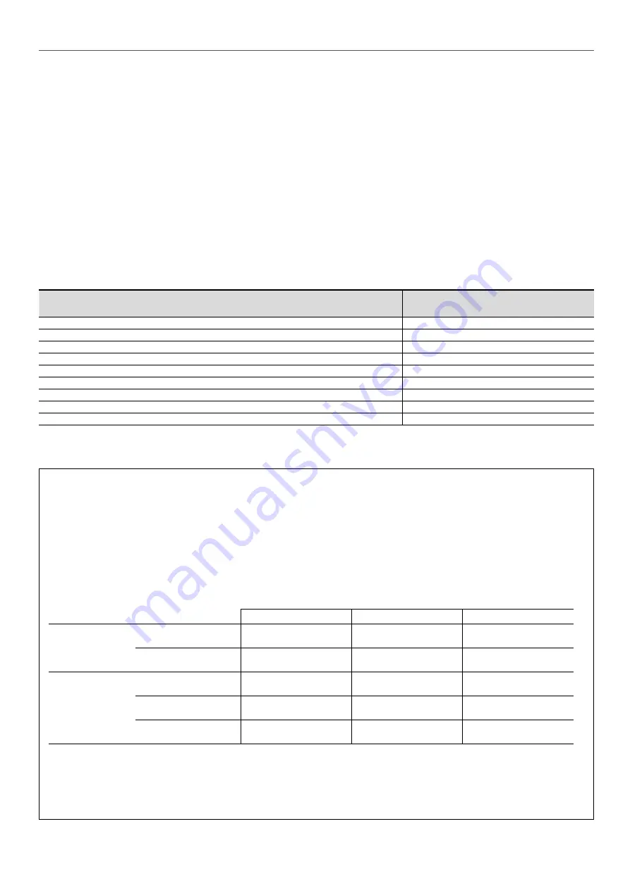
Users  must  ensure  that  periodic  leak  testing  is  carried  out  by  qualified  personnel  based  on  the  number  of  tonnes  of  CO

2


equivalent:

≥ 5 tCO2eq

≥ 50 tCO2eq

≥ 500 tCO2eq

Frequency of check

Without leak detection system

Every 12 months

Every 6 months

Every 3 months

With leak detection system

Every 24 months

Every 12 months 

Every 6 months

Refrigerant 

charge*

R410A (GWP = 2088)

≥ 2.39 kg

≥ 23.9 kg

≥ 239 kg

R407C (GWP = 1800)

≥ 2.77 kg

≥ 27.7 kg

≥ 277 kg

R134a (GWP = 1430)

≥ 3.49 kg

≥ 34.9 kg

≥ 349 kg

*  The refrigerant charge and the number of tonnes of CO

2

 equivalent will be given by the installer.


-

 Users of any system subject to leak testing are required to keep a log of the quantities and types of fluids used, (added or 

recovered), and to include the dates and results of leak tests, as well as the name of the technician and the technician's company.


-

A leak test must be carried out one month after any leak repairs.


-

System users are responsible for collecting used refrigerant and having it recycled, regenerated or destroyed.

13

Summary of Contents for 09PE

Page 1: ...Translation of the original document INSTALLATION OPERATION AND MAINTENANCE INSTRUCTIONS Drycooler and air cooled condenser 09PE...

Page 2: ...eed 8 7 2 Air intake height 9 8 INSTALLATION RECOMMENDATIONS 10 9 CONNECTIONS 10 9 1 Electrical connection 10 9 2 Fluid connection 10 9 3 Connecting a speed regulator 10 10 OPERATION 11 10 1 First com...

Page 3: ...16 16 PROTECTION CABINET OPTION 16 17 CONTROL CABINET WITH ELECTRONIC BOARD OPTION 17 18 ELECTRICS BOX OPTION 18 19 STAGING FOR CONTROL CABINET OPTION 19 20 OPTION FOR CONTROL CABINET CONTROLLED BY TH...

Page 4: ...ublic access by clearly marking the work area 2 1 In an emergency Switch off the electrical supply The process should not be jeopardised if the emergency stop devices are activated Switch off the fans...

Page 5: ...r 9 08 Number of fans 01 to 14 3 Number of rows of finned tubes 2 3 4 or 5 2 Number of fan lines 1 or 2 S Coil specification S single coil D double coil T 2 refrig circuits Z drainable coil H Unit pos...

Page 6: ...d in the table below with a symbol must be lifted using a spreader beam Lifting using a spreader beam Lifting using a crane A A A B B B A B 60 60 E E E E E E 1067 1067 1067 H H H 1023 5 2 Lifting VERT...

Page 7: ...feet must be moved to the use position B To do this Lift the upper unit using the lifting rings Keep the unit raised throughout the procedure Unscrew the 4 mounting bolts on each foot The other bolts...

Page 8: ...t is recommended to place the units in an area protected from adverse weather conditions 7 INSTALLATION Contact us for projects with a special seismic risk Before setting up the unit in its intended l...

Page 9: ...ake perimeter Several units are placed side by side to prevent the risk of air recycling air intake on 4 sides only 1 unit placed against a wall air intake on 3 sides only 1 unit placed against 2 wall...

Page 10: ...ediately contact your energy supplier and make sure the unit is not switched on until the necessary corrective actions have been taken Failure to do so will automatically void the warranty It is your...

Page 11: ...use Scaling and corrosion have a very negative effect on the operation and service life of the units Therefore only use treated water or authorised fluids check the compatibility of any additives with...

Page 12: ...f the voltage drops below 290 V for 5 seconds the motor stops The fault is indicated by a change of state on the KL2 relay The motor will restart when the voltage returns to its nominal value Absence...

Page 13: ...nt 1 year 1 Clean the louvres on the electrical cabinet optional 1 year Expansion vessel optional check that all devices work correctly and check the sealing of all couplings 1 year Check the electric...

Page 14: ...nitial wash against the air flow direction at the discretion of the operator and depending on the fouling level 5 Some detergents may damage the unit s paintwork 14 5 Removing and refitting a fan The...

Page 15: ...semble position the fan on the 12 inserts of the unit then repeat the operations in reverse order to disassembly taking care only to use the screws supplied M8x25 screws flat washer for V shaped units...

Page 16: ...xes are provided for the installer on the base of the cabinet A padlockable front disconnect switch with auxiliary contact fitted with a device requiring the power supply to be switched off before the...

Page 17: ...nd mounted on the front of the unit on the inlet manifold side For electrical connection refer to the connection sheet or wiring diagram supplied with the cabinet The cables to use for the power conne...

Page 18: ...temperature sensor may be added for use from 20 to 40 C Humidity As an option a heater connected to a humidity sensor may be added for use above 60 humidity Information available See connection sheet...

Page 19: ...19 STAGING FOR CONTROL CABINET OPTION 1 or 2 circuits per coil 2 circuits per coil 1 circuit per coil Key M 01 Number of motors 1 Number of stages 19...

Page 20: ...per If cables made from other materials such as aluminium are used bimetallic terminals and connectors or intermediate terminals must be used The electrical connections are to be made as follows Conne...

Page 21: ...M 09 M 11 M 04 M 06 M 08 M 10 M 12 M 02 M 01 M 03 M 05 M 07 M 04 M 06 M 08 M 02 M 01 M 03 M 05 M 04 M 06 M 02 M 01 M 03 M 04 M 02 M 01 M 03 M 05 M 07 M 04 M 06 M 08 M 02 M 01 M 03 M 05 M 04 M 06 M 02...

Page 22: ...ILLING capacity 35 VT 46 15 31 94 31 63 VU USEFUL expansion volume 43 14 29 88 29 59 LOW PRE ALARM capacity 32 VT 42 14 28 86 29 57 LOW PRE ALARM capacity 16 VT 21 7 14 43 14 29 Empty weight kg 44 52...

Page 23: ...unit s supply to the presence of a flow rate detected by a sensor In all cases refer to the general information section of this manual to the specific manuals for the ATEX components built into the u...

Page 24: ...e stopped and the impeller inspected If dust is found all the areas affected must be thoroughly cleaned If the vibration speed level is still compliant with the standardised thresholds the fan may ret...

Page 25: ...the working area In zone 1 and in the presence of substances belonging to group IIC acetylene carbon disulphide hydrogen and hydrogen sulphide ethylene oxide carbon monoxide if there is a risk of exp...

Page 26: ...ilver Fluids to be recovered for recycling Drycoolers MEG MPG Thermal fluid Refrigerant fluid R404 R407A R407C R410A R134a R22 depending on the condenser type Compressor oil Waste electrical and elect...

Page 27: ......

Page 28: ...536634 03 09 2020 replaces No EN7536634 02 04 2020 Produced for CIAT S A Culoz in France The manufacturer reserves the right to modify the product specifications without prior notice Printed in the Eu...

Reviews: