background image


4

 
EVACUATION AND DEHYDRATION 


Evacuation is the most important part of the entire service procedure. 
The life and efficiency of the equipment is dependent  upon the  
evacuation and dehydration thoroughness exercised by the 
serviceman.  
 
Air in the system causes high condensing temperature and pressure, 
resulting in increased power consumption and at the same time it 
reduces system efficiency. Moisture chemically reacts with the 
refrigerant  and oil thus forming corrosive acids which attacks motor 
windings and metal parts, causing early breakdown. 
 
After the system has been leak checked and proven leak free, connect  
the vacuum pump and evacuate system to 29” Hg vacuum. It is 
advisable to connect both vacuum pump hose to the high-side and low-
side of the system to have a better and faster evacuation. 


FINAL LEAK TEST 


After the unit has been properly evacuated and charged, use a halogen 
leak detector to check system for leaks. In the absence of this device 
water-soap solution is acceptable. All piping within the condensing unit, 
evaporator, and interconnecting tubing should be checked for leaks. If a 
leak is detected, the refrigerant should be recovered before repairing the 
leak.  This is in compliance with the Clean Air Act.


WATER PIPING 


Water inlet and outlet are equipped with 25.4mm or 1 “  (FPT)               
female pipe thread. 


Make sure that internal water piping is clean. 


Use correct size wrenches and proper sealing for water inlet 
and outlet connections. 


Do not over tighten the connections. 


Suspend or use vibration isolators on water pipes, for pipes 
not to transmit vibration. 


Field install air bleed valve and dirt leg pipes (for backwashing 
purposes) in water piping system. 


Field install water supply and return line connection and check 
for water pressure drop and flow rates. 


Water piping accessories, water strainer (screen assemblies 
of 20 to 40 mesh) and water flow switch to be field supplied 
and installed.  


Water system needs to be chemically treated in order to 
maintain  water cleanliness and minimize scale build-up. 


After all the water piping is completed, be sure to flush all pipe 
work prior to start-up. 


Condenser water inlet need to be controlled at 29.5

°C

(85

°F

 )

It is advisable to always maintain the water inlet temperature in
this region. This can be accomplished by using a thermostat to
control the cooling tower fan and water temperature in the 
basin of the tower.  

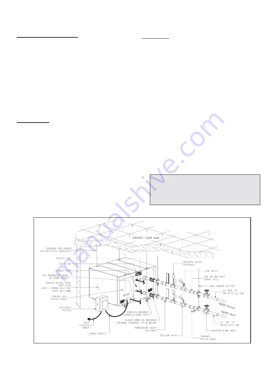
FIG. 5   TYPICAL PIPING & WIRING WORKS 

Summary of Contents for 07KHP

Page 1: ...ny transmission of noise and vibration to the ceiling or walls Provide enough pipe flexibility before fixing unit to the structure Provide access panel in ceiling Make sure the panel is located near the unit for easy maintenance and servicing After the unit is installed and pipe work are completed be sure to insulate the unit s surroundings with acoustic treatment An acoustic type insulation can b...

Page 2: ...8 6 1 1 8 REFRIGERANT CONNECTIONS Liquid mm in Flare Type 6 35 6 35 9 52 3 8 9 52 3 8 9 52 3 8 S 15 8 5 8 High Press PSIG 426 7 320 20 CONTROL PRESSURESTAT SETTINGS Open Close pressure settings Low Press PSIG n a 27 4 67 7 POWER SOURCE V Ph Hz NOMINAL V 208 230 1 60 230 3 60 PERMISSIBLE MIN MAX VOLTAGE V 197 253 REFRIGERANT CONTROL DEVICE IN UNIT Capillary Tube Capillary Accurator RLA Rated Load A...

Page 3: ... supplied and field installed applicable for model 07KHP036 048 060 and 090 only Warranty will be voided if these models were not fitted with external filter drier in the field installation TUBING CONNECTIONS AND LEAK TEST Both suction and liquid are equipped with flare type connections except for Model 090 uses sweat connection Assemble flare joint by aligning tubing with machine surface of fitti...

Page 4: ...eak is detected the refrigerant should be recovered before repairing the leak This is in compliance with the Clean Air Act WATER PIPING Water inlet and outlet are equipped with 25 4mm or 1 FPT female pipe thread Make sure that internal water piping is clean Use correct size wrenches and proper sealing for water inlet and outlet connections Do not over tighten the connections Suspend or use vibrati...

Page 5: ...5 FIG 6 CEILING MOUNTED INSTALLATION FIG 7 FLOOR MOUNTED INSTALLATION ...

Page 6: ...balance is satisfactory as it is below the maximum allowable 2 Operation on improper line voltage or excessive phase imbalance constitutes abuse and may cause damage to electrical components OPERATION AND START UP PRELIMINARY CHECKS Before operating the unit be sure the following are in order 1 All wiring connections are correct and tight 2 All barriers covers and panels are in place 3 Electrical ...

Page 7: ... maintenance LUBRICANT Compressor contains factory oil charge Replace oil when lost See table 3 for oil recharge and refer to Carrier Manual Chapter 1 page 1 21 for oil recharging procedure CLEANING HEAT EXCHANGER Use a tank with 5 phosphoric acid Pump the cleaning liquid through the plate heat exchanger at 1 5 times normal flow rate for optimum cleaning preferably in back flush mode Then rinse wi...

Page 8: ......

Page 9: ...1 1 22 2 23 3 24 4 12 5 6 7 7 8 9 4 11 1 12 8 14 4 16 1 17 8 19 4 20 6 22 2 23 3 25 15 5 3 9 5 6 6 7 8 3 10 11 7 13 3 15 16 7 18 3 19 4 21 1 22 2 23 9 18 3 3 3 5 8 7 2 8 9 10 6 11 7 13 3 15 16 7 18 3 20 21 1 22 8 21 1 7 5 6 7 2 8 9 10 6 11 7 13 3 15 16 7 18 3 20 21 7 23 9 3 3 5 6 7 8 3 10 11 7 13 3 15 6 17 2 18 9 20 6 26 7 2 8 4 4 6 7 8 3 10 11 7 13 9 15 6 17 2 19 4 29 4 4 4 6 1 8 3 10 6 12 2 14 4...

Page 10: ...10 FIG 8 WIRING DIAGRAM 07KHP012 FIG 9 WIRING DIAGRAM 07KHP018 024 ...

Page 11: ...11 FIG 10 WIRING DIAGRAM 07KHP040 050 FIG 11 WIRING DIAGRAM 07KHP060 ...

Page 12: ...12 FIG 12 WIRING DIAGRAM 07KHP090 FIG 13 RECOMMENDED SERVICE CLEARANCES ...

Page 13: ...H LOOSE LEADS AT COMPRESSOR COMPRESSOR STUCK COMPRESSOR POWER SUPPLY OPEN COMPRESSOR INTERNAL PROTECTION OPEN OVERCHARGED OR NONCONDENSABLES IN SYSTEM OPEN SHORTED OR GROUNDED COMPRESSOR MOTOR WINDING HIGH SUPERHEAT COMPRESSOR BEARINGS DEFECTIVE FAN CAPACITOR LINE VOLTAGE TOO HIGH OR LOW LOW REFRIGERANT CHARGED RESTRICTED DISCHARGE LINE INTERNAL PRESSURE RELIEF OPEN DEFECTIVE COMPRESSOR VALVES CON...

Page 14: ...inlupa City Tel No 63 2 850 1367 Fax No 63 2 809 9979 Website www carrier com ph Manufacturer reserve the right to discontinue or change at any time specifications or designs without notice and without incurring obligations Form 07KHP 4IOM Replaces 07KHP 3IOM Concepcion Carrier Air conditioning Company ...

Reviews: