


8–31
62-11785
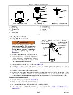
8.8.6
Megohmmeter Test Procedure
Check of the electrical insulation integrity and connections using a resistance tester (commonly known as a
megohmmeter or Megger), such as Carrier Transicold P/N 07-00481-00, that can be set to 1000V.
CAUTION
!
Before connecting a megohmmeter, place the Main Power switch in the OFF position.
Disconnect the high voltage source, lockout/tagout the receptacle and disconnect the negative
battery connection. Isolate the microprocessor by disconnecting all connectors and wires
going to it. Observe National Electric Manufacturer’s Association (NEMA) rules and test
equipment manufacturers instructions.
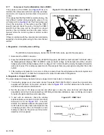
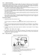
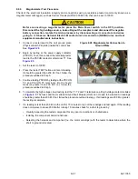
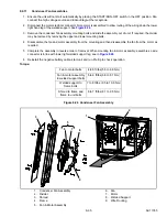
1. Connect a tester lead to the unit ground plate
(Physical Earth, PE plate) inside the control box.
See
.
2. Begin by testing at the power supply contactor
(PSCON). To do this, connect the remaining tester
lead to the PSCON contactor at terminal T1. See
.
3. Set the tester to 1000V.
4. Press the tester TEST button and record reading.
It should be greater than 200 M. If not, follow the
procedure outlined in Step h.
5. Continue testing PSCON by testing at the PSCON
T2 and PSCON T3 terminals. Both should
measure greater than 200 M If not, follow the
procedure outlined in Step h.
Figure 8.20 Megohmmeter Connection to
Ground Plate
6. To complete the high voltage circuit testing, test the T1, T2 and T3 terminals on all high voltage contactors listed
in
. The fuses and the Overload Ground Fault Module (OGF) do not need to be tested. All readings
should be greater than 200 M. If not, follow the procedure outlined in step g. If all readings are 200 M or greater,
the testing is complete.
7. If a reading is less than 200 M run the unit for 15 minutes to dry out the windings and test again. If the reading
does not improve to above 200 M after running 15 minutes, check for a short to ground by:
• Visually inspecting the tested component for any poor connections or chafed wires.
• Isolating the component and wire harness.
• Retesting the harness and component (i.e. the motor windings) with the tester to determine where the
short to ground is located.
Summary of Contents for VECTOR 8100
Page 2: ......
Page 4: ......
Page 12: ...62 11785 viii ...
Page 16: ...62 11640 12 ...
Page 18: ...62 11785 ...
Page 24: ...62 11785 1 6 1 3 SAFETY DECALS ...
Page 25: ...1 7 62 11785 ...
Page 26: ...62 11785 1 8 ...
Page 27: ...1 9 62 11785 ...
Page 28: ...62 11785 1 10 ...
Page 30: ...62 11785 ...
Page 50: ...62 11785 ...
Page 82: ...62 11785 ...
Page 96: ...62 11785 4 14 ...
Page 98: ...62 11785 ...
Page 129: ...5 31 62 11785 ...
Page 130: ...62 11785 5 32 ...
Page 134: ...62 11785 6 4 ...
Page 138: ...62 11785 ...
Page 230: ...62 11785 ...
Page 271: ...8 41 62 11785 ...
Page 272: ...62 11785 8 42 ...
Page 274: ...62 11785 ...
Page 286: ......
Page 287: ......
Page 288: ...62 11785 10 8 ...
Page 292: ......
Page 293: ......