


62-11785
7–34
00121
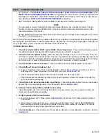
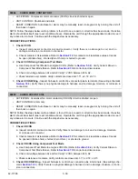
CHECK AMBIENT AIR SENSOR
• ACTIVATION: Ambient Air Temperature Sensor (AAT) is not within range of -53 to +158°F (-47° to +70° C).
• UNIT CONTROL: A value of 122°F (50°C) will be used for any calculations.
• RESET CONDITION: Auto reset when sensor is in range or alarm may be manually reset using the dis-
play mounted keys or by turning the unit off, then back on again.
NOTE: Follow the steps below until a problem is found. Once a repair or correction has been made, the active
alarm should clear itself (refer to reset condition above). Operate the unit through the appropriate modes to see
if any active alarm occurs. Continue with the steps below as necessary.
CORRECTIVE ACTIONS:
1.
Check Sensor
a. Inspect sensor & connector. No damage to sensor. No damage, moisture, or corrosion in connector.
b. Check sensor resistance. (Refer to Note 3 in
Section.) 10,000 Ohms @ 77°F (25°C). Refer
to
for chart of resistances for different sensors.
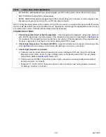
2.
Check Sensor Wiring
a. Inspect connector pins & terminals at sensor and connector 2MM. (See wiring schematic
.) Verify there is no physical damage to harness, and no damage, moisture, or corrosion in
connectors.
b. Place the system in PC Mode. Refer to Note 2 in
Section. Disconnect sensor from harness.
Check for 3.0 ± 0.1 VDC at harness plug between pins. Voltage should be 3.0 ± 0.1 VDC volts at
harness plug between pins. This verifies microprocessor.
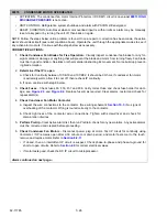
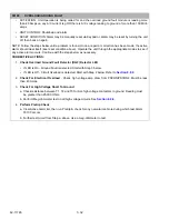
00122
CHECK RETURN AIR SENSOR
• ACTIVATION: Return Air Temperature Sensor (RAT) is not within the range of -53 to +158°F (-47 to +70° C).
• UNIT CONTROL:
• If alarm
is not active: Alarm and switch to supply air control.
• If alarm
is active: Alarm and the System will enter Cargo Pro-
tect Mode. Refer to
• RESET CONDITION: Auto reset when sensor is in range or, alarm may be manually reset using the dis-
play mounted keys or by turning the unit off, then back on again.
NOTE: Follow the steps below until a problem is found. Once a repair or correction has been made, the active
alarm should clear itself (refer to reset condition above). Operate the unit through the appropriate modes to see
if any active alarm occurs. Continue with the steps below as necessary.
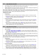
1.
Check Sensor
a. Inspect sensor & connectors. Verify there is no damage to sensor, and no damage, moisture, or
corrosion in connectors.
b. Check sensor resistance. (Refer to Note 3 in
Section.) 10,000 Ohms @ 77°F (25°C). Refer
to
for chart of resistances for different sensors.
2.
Check Sensor Wiring
a. Inspect connector pins & terminals at sensor connector 2MM. (See wiring schematic
.)
Verify there is no physical damage to harness, and no damage, moisture, or corrosion in connectors.
b. Place the system in PC Mode. Refer to Note 2 in
Section. Disconnect sensor from harness.
Check for 3.0 ± 0.1 VDC at harness plug between pins. Voltage should be 3.0 ± 0.1 VDC volts at
harness plug between pins. This verifies microprocessor output and wiring connections to sensor.
Summary of Contents for VECTOR 8100
Page 2: ......
Page 4: ......
Page 12: ...62 11785 viii ...
Page 16: ...62 11640 12 ...
Page 18: ...62 11785 ...
Page 24: ...62 11785 1 6 1 3 SAFETY DECALS ...
Page 25: ...1 7 62 11785 ...
Page 26: ...62 11785 1 8 ...
Page 27: ...1 9 62 11785 ...
Page 28: ...62 11785 1 10 ...
Page 30: ...62 11785 ...
Page 50: ...62 11785 ...
Page 82: ...62 11785 ...
Page 96: ...62 11785 4 14 ...
Page 98: ...62 11785 ...
Page 129: ...5 31 62 11785 ...
Page 130: ...62 11785 5 32 ...
Page 134: ...62 11785 6 4 ...
Page 138: ...62 11785 ...
Page 230: ...62 11785 ...
Page 271: ...8 41 62 11785 ...
Page 272: ...62 11785 8 42 ...
Page 274: ...62 11785 ...
Page 286: ......
Page 287: ......
Page 288: ...62 11785 10 8 ...
Page 292: ......
Page 293: ......