background image

SpeedCheck

®


APPLIED INFORMATION (AI) INTEGRATION INSTALL GUIDE  


Carmanah Technologies Corp. | 250 Bay St, Victoria, BC V9A 3K5, Canada | 1.250.380.0052 

[email protected]

 | 

carmanah.com


For the SPEEDCHECK-12 


90063_INSTALL-GUIDE_SPEEDCHECK-12-AI-Integration-Kit_RevB 

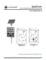
SPEEDCHECK-12 

(Battery/Solar)


SPEEDCHECK-12 

(AC)


Summary of Contents for SPEEDCHECK-12

Page 1: ...L GUIDE Carmanah Technologies Corp 250 Bay St Victoria BC V9A 3K5 Canada 1 250 380 0052 customersupport carmanah com carmanah com For the SPEEDCHECK 12 90063_INSTALL GUIDE_SPEEDCHECK 12 AI Integration Kit_RevB SPEEDCHECK 12 Battery Solar SPEEDCHECK 12 AC ...

Page 2: ...manah Technologies Corp 250 Bay St Victoria BC V9A 3K5 Canada 1 250 380 0052 customersupport carmanah com carmanah com 2 APPLIED INFORMATION AI INTEGRATION INSTALL GUIDE This page left intentionally blank ...

Page 3: ...L GUIDE Table of Contents Table of Contents 3 1 0 Warnings and Precautions 4 1 1 Warranty Disclaimer 4 1 2 Standards 4 1 3 Safety and Usage Precautions 4 1 4 Applications 5 2 0 System Components 6 3 0 Tools and Materials Required 6 4 0 Installation 7 4 1 Opening Rear Enclosure 7 4 2 AI 500 070 Field Control Unit FCU 8 4 3 Solar Version Only 11 4 4 Testing AI FCU 12 ...

Page 4: ...arranty 1 2 Standards Perform all installation wiring grounding and maintenance in conformance with local building and electrical codes Adherence to the National Electrical Code NEC is mandatory to comply with any certification markings Non adherence to code may void the warranty 1 3 Safety and Usage Precautions Batteries are shipped fully charged Use extreme caution when handling the batteries as...

Page 5: ...pport carmanah com to download the complete product user manual 1 4 Applications For Carmanah SPEEDCHECK 12 radar speed signs the AI Integration Kit allows for remote system monitoring scheduling and control The SPEEDCHECK 12 AI Integration Kit is available in two different states of assembly described below If ordered with a SPEEDCHECK 12 system the display enclosure harnessing is assembled in th...

Page 6: ...rness solar monitoring 8 1 4 Nut nyloc 1 4 20 4 5 Cable tie 4 way mounting base 2 6 Cable tie 4 4 7 Cable tie 7 8 screw mount 1 8 Screw 8 32 x 1 4 pan head 3 9 Screw 8 32 x 3 8 pan head 1 10 Adapter 90 SMA male to SMA female 2 3 0 Tools and Materials Required The following tools and materials may be required to install the AI Integration Kit into your SPEEDCHECK 12 system 1 Drill and 17 32 drill b...

Page 7: ...TION AI INTEGRATION INSTALL GUIDE 4 0 Installation 4 1 Opening Rear Enclosure 1 To open SPEEDCHECK 12 insert included key into lock and rotate clockwise 2 Apply diagonal pressure to the bottom right corner of the sign face then PULL on the key 3 Once unlocked the key can be removed 4 Swing the display enclosure away from the rear enclosure ...

Page 8: ...CU mounting plate 1 Disconnect power to the system by opening all battery fuse holders or switch off the breaker to the right 2 Install the AI FCU mounting plate into the rear enclosure and secure with three nyloc nuts in the locations outlined below 3 Drill a 17 32 hole in the top corner of the rear enclosure at the half shear location Deburr both sides of the hole and remove all metal chips 4 Re...

Page 9: ...e tie holders onto the mounting plate as shown below 6 Route coax cables from antenna to cable tie mounts and loop cables around 2 1 4 turns clockwise Secure with four cables ties Coax cable connectors should end up approximately in the left of the rear enclosure 7 Install 16 pin and 4 pin harnesses into the AI FCU 8 Thread two 90 coax adapters onto antenna connectors Orient as shown below ...

Page 10: ...ng terminal onto stud shown and fasten with one nyloc nut Orient as shown 12 Thread GPS and LTE antenna coax harness connectors onto correct connectors on the AI FCU not shown below Yellow sensor wire will remain unterminated for AC powered systems For solar powered systems this will mate with the yellow wire from the solar kit See Section 4 3 for more information 13 Connect the 2 pin and 4 pin AI...

Page 11: ...ere is a length of yellow sensor wire to be routed with the battery harness from the solar kit to the LED display 2 Terminate this yellow sensor wire to the Solar positive terminal of the charge controller Route the sensor wire down the pole and into the rear enclosure 3 Once the sensor wire is inside the rear enclosure connect it to the yellow wire shown below To charge controller Solar To AI FCU...

Page 12: ...ct wiring and power up system by connecting the DC power battery fuses or switch on the breaker and turning on the AI power switch 5 Open your PC open a browser and navigate to the Glance website glance appinfoinc com 6 Log in using the credentials provided by AI or the distributor you purchased the equipment from 7 On the upper left side of the browser select the device name that matches the Devi...

Page 13: ...re Current Device Status is OK 10 Contact Applied Information to arrange the firmware in the AI unit to be programmed correctly if this hasn t already been done a Phone 678 830 2170 b Email support appinfoinc com c Web appinfoinc com 11 To close push the display enclosure against the rear enclosure and then apply diagonal pressure in the bottom right corner of the sign face Once fully closed then ...

Page 14: ...customersupport carmanah com carmanah com 14 APPLIED INFORMATION AI INTEGRATION INSTALL GUIDE 2021 Carmanah Technologies Corporation Technical Support Email customersupport carmanah com Toll Free 1 877 722 8877 US Canada Worldwide 1 250 380 0052 Fax 1 250 380 0062 Web carmanah com ...

Reviews: