Power Connections
(Continued)
The Power Supervisor Unit should now be connected up. The following connections
are required (all are shown on the diagram on Page 14):
• Connection to the ENABLE connectors on each of the Audio and Digital Raw DC
units using the cables supplied (SSL Part No. 66C96105). Be sure to connect the
Power Supervisor end of these cables correctly - to AUDIO ENABLE or DIGITAL
ENABLE
sockets as appropriate.
• Connection to the AUDIO STATUS and DIGITAL STATUS sockets on the Filter
Unit using the cables supplied (SSL Part No. 66C96106).
• Phantom power connection to the PHANTOM INPUT socket on the Filter Unit
using the cable supplied (SSL Part No. 66C96107).
• Connection to the POWER SUPERVISOR socket on the SL 9000 J Processor Rack
using the cable supplied (SSL Part No. 66C96108).
Operating Voltage Setting and Fuse Replacement
Processor
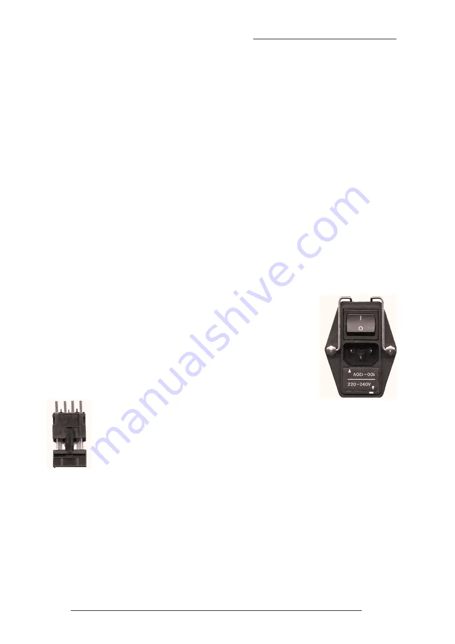
The rear panel Power Input Module is shown opposite. At the
bottom of the module is the fuse holder. SL 9000 J systems are
factory preset for their destination power requirements. The
appropriate 20mm Time Delay fuses must be fitted as follows:
Operating Voltage
Fuse Rating
SSL Part No.
100/120V
5A(T)
35FET350
220/240V
2A(T)
35FEG320
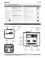
To check or replace a fuse, first remove the combined voltage selection
panel and fuseholder assembly. This will reveal the fuse carrier, which
holds two fuses, one for each of the configurable operating voltages. The
fuse carrier is shown on the left with both fuses in position. The white
arrows on the front of the panel (see picture on the right) point to the fuse
applicable to that operating voltage range.
Fit the fuse carrier back into the Power Input Module so that the white arrow
corresponding to the desired operating voltage points towards the white rectangle in
the bottom right hand corner of the assembly. (The picture above shows the unit
configured for 220/240 V operation.)
Always be sure to replace the fuseholder assembly in the position
corresponding to the correct operating voltage.
16
10.10.97
SL 9000 J Series Console Installation Guide
Summary of Contents for Solid State Logic SL 9000 J Series
Page 1: ...82S6Q9K010B SL 9000 Series Installation Guide V 2 1 2 7 98...
Page 2: ...12 3 97...
Page 3: ...Solid State Logic SL 9000 Series Installation Guide V2 1 2 7 98...
Page 8: ...i8 12 3 97 SL 9000 J Series Console Installation Guide...
Page 9: ...Solid State Logic SL 9000 J Total Studio System Installation Guide 82S6Q9K010B...
Page 44: ...36 18 9 97 SL 9000 J Series Console Installation Guide...