P a g e |
8
3 Equipment description
The sections below describe each individual hardware element of a standard Merlin LT vessel-based lidar system.
3.1 Merlin LT
The Merlin LT unit incorporates a rotating laser range finder which is housed with a motor and encoder in a weather-
proof pod, held between two ‘A-frame’ pillars that sit on a base plate.
3.1.1 Laser
The laser contains the optical and electronic components that allow distance measurements to be recorded to
reflectorless targets up to 250 m from the instrument.
The laser uses a ‘time-of-flight’ method to measure ranges to remote targets.
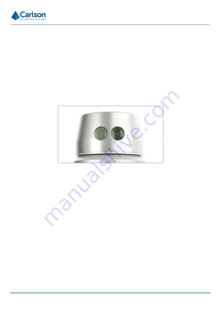
The two lenses visible within the laser module are the transmitting and receiving optics. It is through these optics
that the infrared measuring laser is fired, and its reflected light is received back into the instrument.
The laser measures 36,000 ranges each second, to an accuracy of +/-1 cm.
The laser ranges up to a limit of 250 m to 90% reflective material (e.g., Kodak white card). However, the maximum
achievable range at any given time or location will depend on a number of factors. In some circumstances these
may prevent any readings from being taken:
•
dark, light-absorbent surfaces such as coal;
•
atmospheric conditions such as dust, fog, heavy rain and snow;
•
wet, slick, shiny or very smooth surfaces;
•
an acute angle between the laser and the surface.
The minimum, calibrated range of the laser is 0.5 m. At shorter distances, readings may still be recorded, but their
accuracy may be diminished.
An internal motor physically rotates the laser housing at up to 20 times per second.
An encoder measures the rotational angle of the laser to an accuracy of 0.01°.
Figure 1 Rotating laser module


